
Deep drawn stamping and progressive die stamping serve fundamentally different manufacturing needs. Deep drawing excels at producing seamless, hollow components with uniform wall thickness and depths exceeding part diameter. Progressive die stamping is optimized for high-volume production of flat or contoured parts with complex features formed in sequence. Process selection directly impacts part quality, tooling costs, scrap rates, and production efficiency. The key differentiator is part depth and geometry—deep parts require material flow, while progressive dies perform sequential operations on strip-fed material.
Deep drawn stamping is a metal forming process where a flat sheet metal blank is radially drawn into a die cavity by a punch, creating seamless, hollow parts. The defining characteristic of deep drawing is that the depth of the formed part exceeds its diameter.
The process occurs through multiple stages or “draw reductions” to prevent tearing or wrinkling. Each stage progressively works the material closer to final geometry while controlling thinning and work hardening. The metal flows like a viscous fluid, resulting in uniform wall thickness throughout the part.
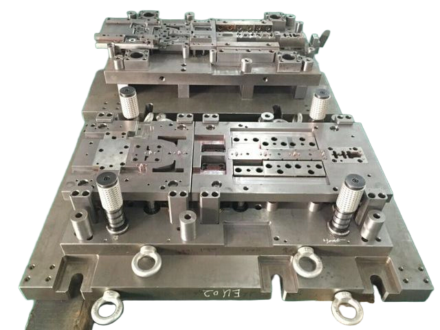
Seamless Construction: Produces parts with no weld joints, seams, or fastener points. This is critical for fluid transfer components, pressure vessels, and housings requiring structural integrity.
Uniform Wall Thickness: The material flow characteristics of deep drawing produce parts with consistent wall thickness and mechanical properties throughout.
Complex Geometries: Creates deep, hollow shapes with complex features that cannot be efficiently produced through other methods.
Work Hardening Benefits: Plastic deformation during drawing increases tensile strength, giving finished parts better strength-to-weight ratios than the flat sheet they originated from.
Smooth Surface Finish: The drawn surface typically exhibits fewer tool marks and interruptions compared to progressive stamping, making deep drawing ideal for visible parts and applications requiring cosmetic quality.
Higher Tooling Costs: Deep drawing dies are more complex and expensive to produce than progressive stamping tooling, particularly for multi-stage draws.
Slower Production Speeds: Deep drawing operates at moderate speeds compared to progressive stamping due to multiple forming stages and controlled material flow.
Material Constraints: Requires highly ductile materials with elongation above 30% and low yield-to-tensile strength ratios below 0.65. Not suitable for brittle metals or high-strength alloys without intermediate annealing.
Specialized Equipment: Requires presses and tooling configurations specific to deep drawing, limiting the number of factories capable of performing the process.
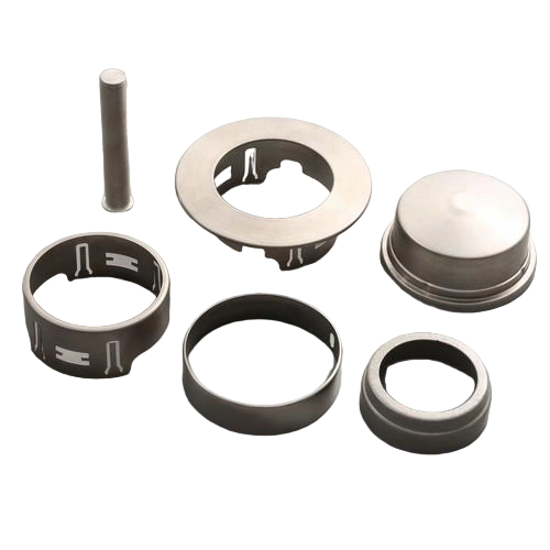
Progressive die stamping is a high-speed manufacturing process where a strip of metal is fed through multiple stations within a single tool. Each station performs one or more operations—blanking, piercing, bending, embossing, coining, or forming—until a finished part emerges at the final station, where it is cut free from the carrier strip.
The process relies on precise strip advancement, typically guided by pilots that engage previously pierced holes to ensure alignment within thousandths of an inch.
High-Speed Production: Capable of producing parts at speeds exceeding 800 parts per minute for simple geometries.
Cost Efficiency at Volume: Once tooling is amortized, per-part costs are significantly lower than deep drawing for compatible geometries.
Complex Feature Combinations: Multiple features—holes, bends, forms, and embossing—can be produced in a single tool, eliminating secondary operations.
Lower Tooling Investment: Progressive dies generally cost less than multi-stage deep draw tooling for parts with shallow features.
Consistent Quality: Automated strip guidance and in-die monitoring systems enable repeatable results across long production runs.
Depth Limitation: The general industry limit for progressive die drawing is approximately 1.5 times the part diameter. Beyond this ratio, the carrier strip connection starves the forming station of material, causing thinning, tearing, and distortion.
Carrier Tab Witness Marks: Each part carries small marks where it separated from the carrier strip. For decorative faces, these marks must be positioned away from view or require secondary finishing.
Station Marks: Multiple forming stations can leave visual witness marks on the part surface.
Material Restriction: Parts are formed while connected to the strip, limiting the ability to perform processes that require the part to leave the strip (beading, necking, flange curling, thread rolling).
Reduced Design Flexibility: Design changes typically require new tooling, adding cost and lead time compared to the iterative nature of deep drawing.
| Feature | Deep Drawn Stamping | Progressive Die Stamping |
|---|---|---|
| Part Depth | Exceeds part diameter; deep, hollow shapes | Shallow or contoured designs; typically depth < 1.5× diameter |
| Production Speed | Moderate (multiple draw stages) | High (up to 800+ parts/min) |
| Tooling Cost | High (complex dies, multi-stage) | Moderate to high (depends on feature count) |
| Wall Thickness | Uniform, consistent mechanical properties | Variable, may have thinning at bends |
| Material Suitability | Ductile, malleable metals (aluminum, stainless, copper) | Wide range, including harder metals |
| Seamless Construction | Yes—no joints or seams | No—features sequential forming |
| Surface Finish | Smooth, minimal tool marks | May have carrier tab marks, station marks |
| Application Fit | Housings, enclosures, fluid components, pressure vessels | Brackets, clips, connectors, multi-feature components |
| Scrap Rate | Lower when properly staged | Can be higher due to carrier strip waste |
| Design Flexibility | Greater for iterative changes | Limited after tooling is committed |
Automotive: Fuel tanks, EV battery housings, brake system components, structural parts exposed to pressure or vibration.
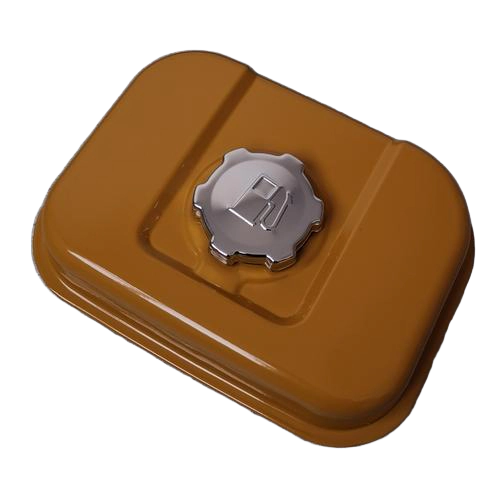
Medical Devices: Metal housings for surgical instruments, implantable device enclosures requiring corrosion resistance and smooth finishes.
Aerospace: Fuel system components, airframe parts, applications requiring strength-to-weight optimization.
Consumer Goods: Beverage cans, kitchen sinks, appliance housings requiring cosmetic finishes.
Fluid Systems: Hydraulic components, fluid transfer parts, pressure vessels.
Automotive: Brackets, clips, fasteners, multi-feature stamped components with stable, high annual usage.
Electronics: Connector shells, EMI shields, precision components for consumer electronics.
Industrial: Hardware, panels, components requiring piercing, bending, and forming in a single tool.
Aerospace: Structural brackets, standard hardware items.
Material Selection: Deep drawing requires materials with high anisotropy (r-value above 1.6) and elongation above 30%. Materials with low yield-to-tensile strength ratios (below 0.65) perform best.
Punch and Die Radii: For deep drawing, die entry radius should be 4 to 10 times material thickness to control material flow and stress concentration.
Draw Reduction Planning: Respect material limits for each draw stage. Aggressive reductions cause tearing; insufficient reductions increase cost through additional stages.
Lubrication Strategy: Deep drawing requires effective lubrication to reduce coefficient of friction from 0.15 to 0.05, lowering punch load requirements by up to 30%.
Tolerance Considerations: Progressive stamping can achieve tight tolerances, but springback and tool wear must be accounted for. Deep drawing delivers consistent dimensional accuracy but requires careful die design to manage thinning.
Industry Standards: Reference ISO 2768 for general tolerance guidance. Regulated industries (automotive, medical, aerospace) typically require specific quality management system certification.
Deep drawing is a metal forming process that produces seamless, hollow parts with depths exceeding their diameter by drawing material into a die cavity. Progressive stamping is a high-speed process where a strip of metal passes through multiple stations, each performing an operation, to form flat or contoured parts. The primary difference is part depth—deep drawing creates deep, hollow shapes while progressive stamping is for shallow or contoured designs.
Deep drawing is the preferred process for deep, cylindrical parts. The general rule is that if part depth exceeds approximately 1.5 times the diameter, a progressive die will struggle with tearing and distortion due to the carrier strip restricting material flow. Deep drawing allows the blank to move freely, pulling metal into the cavity through staged reductions.
The limiting draw ratio (LDR) is the maximum blank diameter to punch diameter ratio achievable in a single drawing operation without failure. For most ductile metals, LDR ranges from 1.8 to 2.3 in a single operation. Parts requiring deeper draws need multiple stages with intermediate annealing.
Deep drawing typically has higher initial tooling costs due to more complex dies and specialized equipment. However, for compatible geometries, deep drawing can produce parts more cost-effectively at production volumes when factors like scrap rate, secondary operations, and part performance are accounted for. Forcing deep parts through progressive stamping can cause 40% scrap rates, eroding any tooling savings.
Deep drawing requires highly ductile, malleable metals. Common materials include aluminum (1100, 3003), stainless steel (300 series), copper alloys, low-carbon steel, and certain titanium and nickel alloys. Materials should have elongation above 30% and low yield-to-tensile strength ratios.
Deep drawing generally yields smoother surface finishes with fewer tool marks, making it ideal for cosmetic applications like visible housings. Progressive stamping produces clean sheared edges but can leave carrier tab marks and station witness marks. For parts with decorative faces, the tab position must be planned away from visible areas or secondary finishing is required.
Progressive stamping is faster, capable of producing over 800 parts per minute for simple geometries. Deep drawing operates at moderate speeds—typically 15 to 40 strokes per minute—due to the multiple forming stages and controlled material flow required to prevent defects.
Aluminum is one of the most requested materials for deep-drawn parts, and for good reason. It combines a strong strength-to-weight ratio with natural corrosion resistance and full recyclability, which makes it a practical choice across automotive, electronics, HVAC, and industrial equipment applications. At Balford, aluminum deep drawing is a core part of our metal stamping capability, and understanding why the material performs well — and how the process actually works — helps when you’re specifying a new part.
A few properties make aluminum a strong candidate whenever a component needs to be both light and durable:
Deep drawing differs from simple stamping or stretching because it reshapes a flat aluminum blank into a three-dimensional part where the depth is equal to or greater than the part’s width — a distinction that matters because aluminum, unlike more elastic materials, resists flow under compression and needs a controlled process to form correctly.
A few factors are worth discussing with your manufacturing partner before finalizing a drawing:
Addressing these upfront avoids costly tooling revisions later and shortens the path from prototype to production.
Balford produces deep-drawn aluminum components for customers across automotive, HVAC, sensor, and industrial equipment applications, supporting projects from initial prototyping through CNC mass production under TS16949 and ISO9001:2015 standards. Our tooling and process engineering teams work with customers early in the design stage to confirm draw ratios, material specification, and finishing requirements before production begins.
Have a drawing for an aluminum deep-drawn part? Request a quote and our engineering team can review it and recommend the right process.
Fuel metering unit (FMU) valves — also known as metering proportional valves — sit at the fuel inlet of high-pressure common rail fuel pumps, where they regulate fuel supply and pressure under ECU control. They’re widely used in electronically controlled diesel engines running Bosch-type common rail injection systems, as well as in aircraft turbine fuel systems where precise flow control is equally critical.
What’s easy to overlook is that most FMU valve failures in the field trace back to two things: material selection and manufacturing precision in the valve housing and internal components. A metering valve doesn’t just need to look right on a drawing — it needs tight dimensional control, clean sealing surfaces, and a housing that holds its shape under repeated pressure cycling. Get any of those wrong at the manufacturing stage, and the downstream result shows up as drive-circuit fault codes, inconsistent fuel delivery, or premature wear — the kind of symptoms that eventually get diagnosed as “valve failure” in the field.
The metering valve and its companion overflow valve are the two components with the highest failure rate in a Bosch-style high-pressure fuel pump. When a fault is traced to one of these parts, the housing itself is often a contributing factor:
Producing a reliable FMU valve housing generally involves:
This is the same process chain Balford uses across our deep drawing and precision stamping lines for other pressure- and fluid-critical components — solenoid valve housings, sensor housings, and similar parts for automotive and industrial customers.
If you’re specifying or sourcing FMU valve housings or similar precision-formed components, a few questions are worth asking any potential manufacturing partner:
Balford manufactures precision deep-drawn and machined components for fuel system, solenoid valve, and sensor housing applications, supporting customers from prototype through mass production under TS16949 and ISO9001:2015 standards.
Interested in sourcing precision valve housings or similar deep-drawn components? Request a quote and our engineering team can review your drawing and specify the right process.
CNC tube bending turns straight round, square or formed tubing into a controlled three-dimensional component. The challenge is that the cross-section and wall do not remain perfectly unchanged. Material stretches on the outside of the bend, compresses on the inside and recovers after the tooling is released.
A strong tube drawing therefore defines more than the final centerline path. It connects material, diameter, wall thickness, bend radius, straight tangents and inspection requirements to a feasible bending route.
Tube geometry is commonly described by the centerline radius, bend angle and rotations between bends. A centerline coordinate table or a controlled 3D model helps prevent ambiguity. Identify the start and end references, orientation of asymmetric features and whether dimensions apply before or after end forming.
A tighter radius relative to tube diameter increases the risk of flattening, wrinkling and wall thinning. The selected radius must suit the material, wall and tooling. Standardizing radii across a part family can reduce tool changes and simplify development.
If a very tight package space drives the radius, identify that constraint during review. A design change to the route, tube size or adjacent assembly may provide a more stable solution than forcing a marginal bend.
The outside wall becomes thinner as it stretches. The inside wall is compressed and may wrinkle if it is not supported. The circular cross-section can become oval. These effects depend on the relationship between outside diameter, wall thickness, radius, material and bend angle.
Mandrels, wiper dies, pressure dies and controlled boost can support demanding bends. Their use affects straight-length requirements, tooling access and cycle planning. Specify the functional limit for ovality or minimum wall only where the application requires it.
The tooling must grip and support the tube around each bend. Very short straight sections between bends or next to an end feature may not provide enough contact. Closely spaced bends can also cause interference between the part and machine.
When packaging permits, add straight tangent length. If the design cannot change, supply the complete 3D model so tooling and sequence can be reviewed before release.
After unloading, the tube tends to open and rotate slightly. Springback varies with material batch, strength, tube geometry and bend conditions. CNC programs compensate through overbending and rotation correction, but the process must first be established with the selected material.
Changing from annealed to harder material, or switching wall thickness while keeping the same outside diameter, can require new compensation values.
A hole or slot close to the bend can distort. A feature cut before bending may move relative to the finished centerline, while a feature added afterward requires suitable access. Decide whether laser tube cutting, drilling, punching or machining occurs before or after forming.
End flares, beads, swages and welded fittings also influence gripping and inspection. Show the desired final relationship rather than separating each operation into unrelated drawings.
Welded tubing may behave differently depending on seam position and consistency. If seam orientation matters to appearance, strength or a subsequent feature, include it as a controlled requirement. Material specifications should cover the tube standard, grade, dimensions and supplied condition.
Use functional datums on mounting faces or end connections. Avoid over-dimensioning every point along the centerline when overall envelope, end position and interface orientation are what control assembly.
Inspection may use gauges, fixtures, coordinate measurement or optical methods. The drawing should define what must be controlled without prescribing a method that cannot access the finished tube.
No. Material, diameter, wall thickness, cross-section and tooling all influence a feasible radius.
They give the clamp, pressure die and support tooling enough contact to control the tube during forming.
It depends on their location, tolerance and access. The cutting and bending teams should review the complete component together.
Explore Balford’s CNC tube bending service, then send the model and drawing for a project review.
A component can meet every individual drawing dimension and still create trouble during assembly. Hole patterns may not align, fasteners may be inaccessible, variation may accumulate across several parts or left- and right-hand components may be mixed. Designing for assembly treats the finished module as a system rather than a collection of isolated pieces.
This guide covers practical decisions for stamped, machined and sheet metal parts that will be joined into a subassembly.
Identify which surfaces locate the module, transmit load, seal, guide movement or establish external appearance. Those interfaces should receive the clearest datums and controls. Features that do not affect the assembly can usually use broader general tolerances.
An assembly drawing should also show orientation, component revision and the relationship between critical interfaces. Do not rely only on the individual part drawings to explain the finished result.
Parts should locate from stable and repeatable surfaces. A primary plane, secondary edge and tertiary feature can constrain the required directions without over-locating the component. If inspection uses one datum system while the assembly fixture uses another, acceptable parts may still fit poorly.
Coordinate the datum strategy across stamped, bent and machined components. A hole created before bending may move relative to a flange, while a machined hole added after forming can be referenced to the final geometry.
Variation accumulates when several dimensions and parts act in the same direction. Review the worst functional condition, not just each nominal value. The response may involve changing the dimensioning scheme, adjusting clearance, controlling fewer critical features or adding an assembly adjustment.
Avoid solving every stack-up by tightening every part. That approach increases manufacturing and inspection effort. Place the tight control where it most directly protects function.
Mechanical fasteners, riveting, clinching, welding, brazing, adhesive bonding and formed tabs each have different access, material and service requirements.
A fastener that is visible in the CAD model may still be unreachable by a driver, wrench, welding torch or inspection probe. Check approach direction, tool diameter, operator hand clearance and the sequence in which nearby components are installed.
Inspection access matters as well. A critical joint hidden after final assembly may need to be verified at an earlier station or controlled through a process parameter.
Asymmetrical hole patterns, keyed tabs, distinct connectors and one-way locating features can prevent incorrect orientation. The feature should be obvious and robust enough to work under normal production conditions. A tiny visual difference may not prevent an operator from assembling the wrong hand.
Weld sequence, joint length, heat input and fixture restraint influence final geometry. Avoid placing all welds on one side of a flexible structure when the design can balance them. Provide realistic fit-up gaps and identify the surfaces that must remain free of spatter or discoloration.
If a machined or sealed interface is critical, consider whether it should be finished after welding.
Specify fasteners, inserts, seals and connectors by an unambiguous standard or approved part number. Check that coatings and materials are compatible with the joined parts and service environment. The assembly bill of materials should match the drawing revision.
Clearance should support the real locating strategy. Too little prevents fit, while uncontrolled clearance can allow movement or inconsistent alignment.
Inspect characteristics at the earliest stage where they are complete and still accessible. Final inspection should confirm the finished module’s function and interfaces.
Balford can coordinate sheet metal processing, machined components and assembly and subassembly around a controlled drawing package. Contact the team to review your module.
A bent sheet metal component begins as a flat blank, but the material does not simply fold along a mathematical line. The outer surface stretches, the inner surface compresses and a region between them changes length much less. Bend allowance and springback calculations connect the finished geometry to the blank and forming process.
This guide explains the main terms and the drawing choices that help Balford evaluate a custom bent part.
The neutral axis is the region through the sheet thickness that experiences little longitudinal strain during bending. Its location is commonly represented by a K-factor. That factor is not a universal material constant; it changes with material, thickness, inside radius, tooling and forming method.
Bend allowance is the arc length along the neutral axis through the bend. A common planning expression is:
Bend allowance = bend angle in radians × (inside radius + K-factor × material thickness)
Bend deduction is another way to relate the outside flange dimensions to the flat blank. CAD systems may use either method. The important point is to use values that match the actual material and tooling rather than relying indefinitely on a generic default.
After the forming load is removed, elastic strain recovers and the bend opens slightly. The amount of springback depends on material strength, elastic modulus, thickness, bend radius, angle and forming method. High-strength materials and large radius-to-thickness relationships often need closer review.
Production processes compensate through tooling angle, overbending, bottoming, coining or programmed correction. The best strategy depends on the component, material and acceptable surface condition.
An extremely small inside radius can increase thinning, cracking and tool pressure. A very large radius can increase springback and make angle control more sensitive. Select the radius around material behavior and function, then confirm that the required tooling is available.
If several bends can use the same radius, setup and tooling may be simplified. If a special radius is essential, mark it clearly and identify whether it is an inspection characteristic.
Holes, slots, notches and embosses close to a bend may stretch or rotate during forming. Moving them farther away, adding relief or producing them after bending can protect the geometry. The correct choice depends on cost, access and tolerance.
Bend relief at the end of a flange can prevent tearing and unwanted material buildup. Relief shape should avoid leaving a crack-like corner or a cosmetic defect in the finished assembly.
Rolled sheet has directional properties. Bending parallel to the rolling direction may produce a different cracking risk than bending across it, especially for harder tempers and tight radii. If grain orientation matters, include it in the nesting and drawing requirements.
Material grade alone may not define formability. Temper, hardness, prior processing and surface coating can all change how a sheet behaves.
Dimension the final functional geometry rather than over-controlling an unverified flat pattern. Use a logical datum scheme for mounting faces, hole patterns and assembly interfaces. Angle, profile and position controls may communicate function more clearly than long chains of linear dimensions.
State whether dimensions apply in a free state or while the part is restrained. Thin or asymmetric parts may relax when removed from a fixture.
For a new material or geometry, sample bends can establish the actual bend allowance and springback. Those results feed the flat pattern and machine program. During production, first-piece and periodic inspections can track angle, flange length and critical feature position.
A stable revision-controlled flat pattern should be linked to the approved material and tooling route. Changing a supplier, sheet condition or bend method may require the values to be verified again.
No. It is a process-planning value influenced by material and forming conditions. Production data or sample bends provide a stronger basis than a universal default.
It can be compensated and controlled, but the chosen method must suit the material, geometry, surface and tooling.
The design team should define the finished functional geometry. The manufacturing flat pattern should then be verified against the selected bending process.
Developing a bent metal enclosure, bracket or profile? Send Balford the drawing for a process and manufacturability review.
Cutting is often the first operation in a sheet metal project, but it affects almost every step that follows. The selected process influences edge condition, heat input, burr direction, nesting efficiency, forming accuracy and assembly fit. There is no single best method for every drawing.
This overview compares practical sheet metal cutting methods and explains the information needed to select a stable route for custom parts.
A flat blank should not be evaluated in isolation. Ask whether it will be bent, welded, inserted into a fixture, coated or assembled to another component. A small change to tab shape, hole position or grain direction can improve the later operation even if the cutting time remains similar.
The correct blank also includes forming allowances. If a bent part is supplied as a finished 3D model, the manufacturer will review the flat pattern against material behavior and the selected bending tools.
Laser cutting is flexible for profiles, holes, slots and frequent design changes. It requires no dedicated cutting tool for each shape, making it useful for prototypes and a wide range of production quantities. Nesting software can arrange parts to improve material use.
Material type, thickness, assist gas and cutting parameters affect the edge and heat-affected zone. Very small holes, narrow webs and heat-sensitive features should be reviewed instead of assumed to behave like larger geometry.
Shearing is efficient for straight cuts and rectangular blanks. It can prepare stock quickly with little programming, but it does not create complex contours. Blade clearance and material condition influence burr, rollover and distortion.
For a component that begins as a simple rectangle and receives features later, shearing may be more practical than contour cutting the entire perimeter.
Turret punching uses standard or dedicated tools to create holes, louvers, slots and profiles. It can combine cutting with certain formed features. The process is productive when geometry and quantity suit the available tooling.
Repeated overlapping hits can approximate a contour through nibbling, but the edge may show witness marks. The drawing should distinguish between functional edges and cosmetic surfaces.
Sawing is commonly associated with plate, bar or tube rather than thin sheet, but it can be useful for heavier flat stock and straight preparation cuts. Mechanical routers or other specialized methods may be considered for particular nonferrous materials or laminate structures.
Carbon steel, stainless steel, aluminum, copper alloys and coated sheets respond differently to thermal and mechanical cutting. State the full grade, thickness and supplied condition rather than describing the material only as “steel” or “aluminum.”
Small holes, narrow slots and short distances from an edge can distort or leave insufficient material for later bending. Review these features relative to sheet thickness and the chosen process.
Most cutting processes can leave some burr, dross, rollover or heat tint. Define where an edge is exposed, used for sealing or inserted into another part. A general “burr free” note is less useful than a measurable edge-break or application requirement.
Tool-free profile cutting supports changes and mixed part families. Dedicated tools can become efficient at stable production volumes. Forecast quantity and expected revisions help determine whether flexibility or cycle time should dominate the decision.
Keep holes, slots and notches away from bend deformation zones where possible. If they must be near a bend, the sequence may need to change or relief may be required. Grain direction can affect cracking and springback in some materials, so note cosmetic or directional requirements on the drawing.
Coordinate the flat pattern with the metal bending process rather than locking an unverified blank size too early.
The answer depends on geometry, material, thickness, quantity and downstream work. A process with a low cutting time may still be expensive if it creates extra deburring or forming problems.
A flat pattern is useful, but the finished 3D geometry and bend requirements should also be supplied so the manufacturer can verify allowances.
Need blanks or finished sheet metal parts? Review Balford’s sheet cutting service or send your drawing for a quotation.
Wire electrical discharge machining removes material with controlled electrical discharges between a thin wire electrode and the workpiece. Because the process does not rely on conventional cutting force, it is valuable for hard materials, delicate sections and profiles that are difficult to reach with a milling cutter.
This Wire EDM machining guide outlines when the process is appropriate, what limitations should be considered and which drawing details help a supplier plan the work correctly.
The workpiece and wire are separated by a small controlled gap in dielectric fluid. Electrical discharges erode tiny amounts of material while the machine guides the wire along the programmed path. The wire is continuously fed, so a fresh electrode surface enters the cutting zone.
The material must be electrically conductive. Tool steels, stainless steels, copper alloys, aluminum and many conductive hard alloys can be processed, while ordinary plastics, ceramics and other nonconductive materials cannot be cut by standard Wire EDM.
For a closed internal opening, the wire must first pass through a start hole. That hole may be drilled conventionally or produced by a small-hole EDM process. Its position, diameter and relationship to the finished contour should be considered in the manufacturing plan.
An open external profile can often be approached from the edge. However, the cut-off section must remain controlled so that it does not move, trap the wire or damage the finished surface at the end of the cut.
The programmed path compensates for wire diameter and the discharge gap. Together they determine the effective kerf. Internal corners cannot be mathematically sharp; their minimum radius depends on the chosen wire and process conditions.
Wire EDM can also cut controlled tapers on suitable geometry. If the upper and lower profiles differ, provide both contours and identify the reference height. Large tapers, thick workpieces and abrupt profile changes may require additional process review.
A first cut removes the main material. One or more skim cuts can then refine size and surface condition with lower discharge energy. Additional passes increase machine time, so tolerance and finish should match the real function of the part.
Accuracy is influenced by workpiece thickness, flushing, thermal stability, wire condition, feature geometry and how the component is supported. A tight tolerance on one functional profile is different from applying the same tolerance to every cut edge.
Although cutting force is low, the electrical process creates a thin thermally affected surface layer. The importance of that layer depends on the material and application. Critical tooling, fatigue-sensitive components or special surfaces may require a defined skim-cut strategy, polishing or another finishing operation.
Heat treatment can also release stress and move the blank. Discuss whether rough machining, stress relief, hardening and final Wire EDM should occur in a specific order.
CNC milling is often efficient for open pockets, faces and accessible three-dimensional features. Wire EDM becomes attractive when the material is conductive and hard, the profile is through-cut, internal radii are small or cutting force must be minimized. Many components use both processes.
It can process many metals and conductive alloys, but conductivity, thickness, heat treatment and application requirements should be reviewed before selecting the process.
A closed internal contour normally requires a start hole so the wire can be threaded through the workpiece.
Provide the CAD profile, drawing, material, thickness, heat treatment, quantity, tolerance and surface requirement. Balford can review the project against its Wire EDM service.
Have a precision profile to manufacture? Send the drawing to Balford for process review.
CNC milling can produce precise faces, pockets, slots, holes and multi-surface features, but a part that is easy to model is not always easy to manufacture. A useful drawing must account for cutter access, workholding, tool stiffness and inspection. Making those decisions early usually leads to a more stable process and a clearer quotation.
This CNC milling design guide explains the issues Balford reviews when evaluating a custom metal component. The aim is not to force every part into a simple shape. It is to separate features that carry real functional value from details that add setups, special tools or unnecessary machining time.
Identify the faces, holes and interfaces that control how the component fits or moves in the final assembly. These features should determine the primary datums on the drawing. A clear datum structure gives manufacturing and inspection teams a shared reference and reduces ambiguity between individual dimensions.
A rotating end mill needs space to enter, move and leave the cut. Deep narrow pockets, hidden undercuts and enclosed corners may require long-reach or custom tooling. Longer tools are less rigid, so feeds may need to be reduced to control deflection and vibration.
Whenever possible, provide open access from a principal direction. If a feature can only be reached after the part is turned, explain whether its relationship to the first setup is critical. This helps determine whether a simple second setup, a fixture or multi-axis machining is appropriate.
An end mill creates a radius in an internal vertical corner. A perfectly sharp internal corner therefore requires another process, such as Wire EDM, or a design change. Increasing the radius lets the shop use a larger and stiffer cutter, which can improve cycle time and surface consistency.
Do not make the corner radius exactly equal to the intended cutter radius. Some clearance allows the toolpath to move through the corner instead of stopping and changing direction abruptly. If a mating component is square, a relief feature or localized clearance may solve the assembly requirement more efficiently.
Deep pockets increase tool overhang and make chip evacuation more difficult. Thin walls can move under cutting force or after residual stress is released. When both occur in the same part, the process may need staged roughing, controlled finishing passes and additional inspection.
Where the design permits, increase wall thickness, reduce pocket depth or add a generous corner radius. For a flexible feature, specify its functional requirement rather than applying an extremely tight general tolerance to every surface.
The part must be held without blocking important surfaces or distorting the material. Include temporary stock, clamping pads or sacrificial tabs when necessary, especially for thin plates and irregular profiles. A component that requires every face to be machined may need multiple setups, soft jaws or a dedicated fixture.
Stable workholding also affects repeat orders. A defined locating strategy makes it easier to reproduce the relationship between machined features across batches.
Tight tolerances affect tooling, setup, thermal control and inspection. They should be reserved for dimensions that influence fit, sealing, motion or alignment. A general tolerance can cover noncritical dimensions, while geometric controls can describe flatness, position, perpendicularity or runout more clearly than many coordinate dimensions.
Surface-finish requirements should also be functional. A cosmetic face, bearing surface and gasket interface have different needs. Mark them individually instead of assigning the finest finish to the entire component.
State the material grade, condition and any traceability requirement. Aluminum, carbon steel, stainless steel, copper alloys and engineering plastics behave differently during machining. Heat treatment and coating can also influence dimensions, surface preparation and the order of operations.
If anodizing, plating, passivation or painting is required, identify masked areas and whether the final dimensions apply before or after finishing.
Not directly with a standard rotating end mill. The design normally uses a radius, a relief feature or a secondary process such as Wire EDM.
Every setup requires locating, clamping, verification and machining time. A design that can be completed in fewer stable setups is usually easier to control and repeat.
Send a 3D model, dimensioned drawing, material, finish, quantity and the features that are functionally critical. Balford can then review the part against its CNC milling service and related manufacturing options.
Planning a machined component? Share your drawing with Balford for a manufacturability review and quotation.
Custom Machined Parts – Built Around Your Needs
We work directly with you to figure out exactly what kind of part you need. Once we understand your requirements, we manufacture it in our advanced machining facilities. We’re a trusted machining company, and we take real pride in delivering parts and production methods that make sense for your business.
Engineered Fasteners & Components
Together with our global network of suppliers, we design fastening solutions that fit your specific application. Our capabilities include:
When you work with us, we’ll find the most practical machining and engineering approach for your project.
Finishes & Extra Processing Steps
We help you choose and develop coating systems that give your parts the right properties—whether you need corrosion resistance, better lubrication, or protection from UV light. Options include dip‑spin coating, electrocoating, zinc plating, and topcoats. Our design and engineering support covers many different types of applications.
We also offer additional machining services to finish your components: turning, grinding, drilling, and shaving. And to save you time and labour, we can handle kitting and assembly as well—so you get more done with less effort.
Materials for Tough Conditions
We supply specialised alloy materials that stand up to extreme environments—very high temperatures, freezing cold, heavy stress, or severe corrosion. Whatever your operating conditions, we have the right material for the job.