Custom Sheet Metal Fabrication in China
Balford fabricates custom sheet metal parts to drawing in China: laser cutting, CNC punching and shearing, CNC and press-brake bending, welding, hardware insertion, tube bending and tube fabrication, surface finishing and assembly - from a single prototype to repeat production.
Send Your DrawingCustom sheet metal fabrication
Every sheet metal enquiry starts with the drawing, not with a catalogue. Balford reviews the material, the blank size, the bend sequence, the welding and finishing route and the tolerances that actually matter on the part before quoting, then runs the work from a single prototype and pre-production sample through to repeat production - to your drawing, or with ODM support where the design is still open.
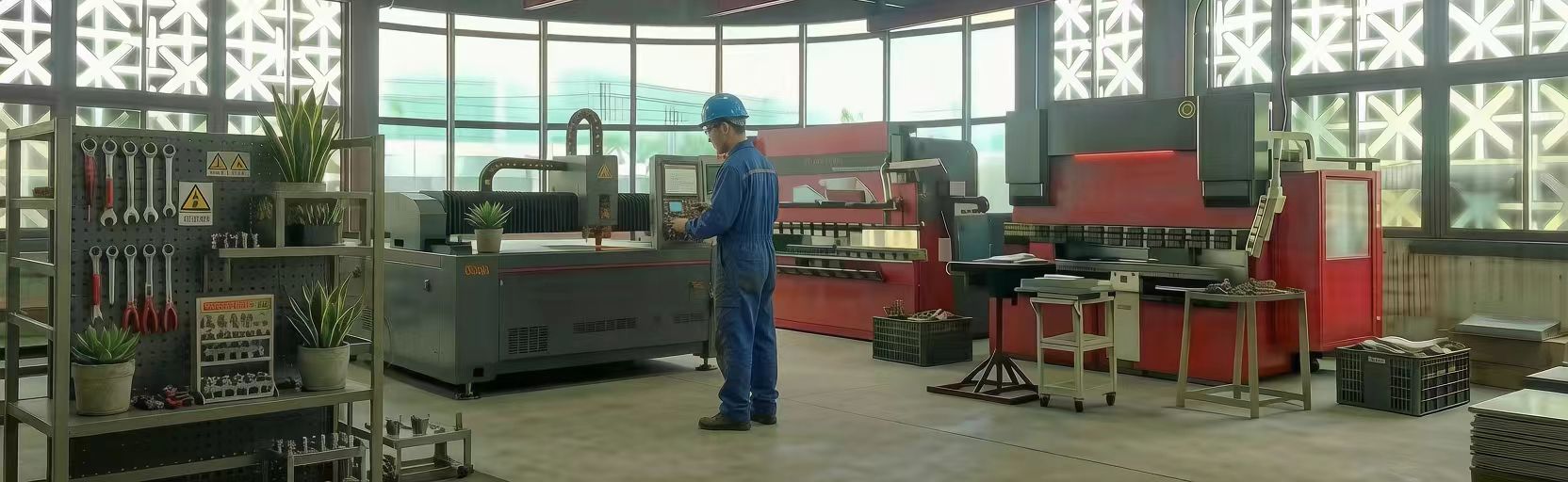
Sheet metal processes in one workflow
Profiles, cut-outs and one-off parts without a die.
Repeated profiles, hole patterns and louvers.
Straight cuts and blank preparation.
Press-brake bending with controlled angle correction.
TIG, MIG and spot welding, sequenced to control distortion.
Rivet nuts, weld studs, standoffs and threaded inserts.
CNC tube bending, tube laser cutting, tube forming and tube welding.
Powder coating, plating, passivation, anodising, brushing and polishing.
Subassembly and final assembly, checked before packing.
Tube bending and tube fabrication sit inside Balford's sheet metal capabilities, not beside them, so a frame that is half sheet and half tube is reviewed on one drawing.
Sheet, plate and tube materials
Material is confirmed against the application, not against price alone, and the grade and its certificate are stated on the quotation.
Mild steel, carbon steel, cold-rolled sheet, galvanised steel.
304 and 316L type grades for corrosion-resistant panels, brackets and housings.
Sheet, plate and tube where weight matters.
Electrical and thermal parts.
Galvanised and coated stock where the coating is functional.
Surface finishing
Finishing is specified with the part's service conditions in mind and stated on the quotation. Bulk finishing - powder coating, plating, passivation, phosphating and painting - is performed by audited partner companies and declared as such, so the finishing route and its lead time are known before the order is placed rather than discovered afterwards. Deburring and edge preparation run ahead of any coating.
Sheet metal applications
Fabricated sheet metal usually arrives from the same places: equipment that needs a rigid frame or a clean enclosure, and cabinets and panels that have to meet a drawing and a finish standard. Typical part families are enclosures, cabinets, brackets, frames, chassis, covers, guards, trays and equipment housings.
Machine frames, guards and covers.
Enclosures, panels and mounting plates.
Cabinets, housings and heat-exchanger frames.
Brackets, supports and shields.
Lightweight frames and sensor mounts.
Chassis and rack components.
Where a programme sits in regulated medical or aerospace territory, say so at enquiry stage: Balford's first-hand experience in those two fields is limited to a small number of programmes, and that is stated rather than implied.
DFM for sheet metal
The cheapest sheet metal part is designed before it is quoted. Balford reviews the drawing for the points that decide whether a part fabricates cleanly or fights the tooling, and returns those findings with the quotation.
Formability, corrosion duty, weight, finishing compatibility.
Inside radius should suit the material and thickness, not the smallest radius the tool can attempt.
The flat pattern depends on both; developed length must be defined, not assumed.
Keeps holes from distorting and from pulling out of shape during bending.
A flange shorter than the tooling can grip cannot be formed reliably.
State what the assembly needs; stacked bend tolerances add up quickly.
Torch access, distortion control and post-weld straightening.
Coating thickness, masking areas and the effect on the tolerance stack.
Fewer set-ups, common thicknesses, nested blanks, standard hardware.
From drawing to finished part
The route is fixed at quotation and does not change silently afterwards.
- 01
2D / 3D drawing and requirements received
- 02
DFM review: material, blank, bend sequence, welding, finishing
- 03
Material selection and certificate confirmation
- 04
Laser cutting, CNC punching or shearing
- 05
Bending on CNC press brakes
- 06
Welding, hardware insertion and subassembly
- 07
Surface finishing (partner operations declared on the quote)
- 08
Inspection against the drawing: dimensions, angles, finish
- 09
Assembly, packing and shipping
Which process does your part need?
Start from the geometry, because the process decides the tooling cost, the lead time and the price structure.
Low tooling cost, fast route, economical from one piece to medium volume.
STRIP, HIGH VOLUMEMetal stampingTooling amortised across the volume instead of the part.
TIGHT TOLERANCE, FROM STRIPPrecision metal stampingPurpose-built tooling holds tolerances fabrication cannot repeat.
DEEP CYLINDRICAL WALLDeep drawingThe wall is formed by material flow, seamless and repeatable at volume.
TUBE OR PIPETube bending and fabricationTube is cut and formed as tube, then welded into the assembly.
SOLID BLOCK, ROTATIONALCNC machiningMaterial is removed, not formed; suits features a bend cannot produce.
Sheet metal and tube capabilities
Laser, CNC punching and shearing.
BENDINGSheet metal bendingCNC press-brake bending.
TUBETube bendingTube bending services.
TUBECNC tube bending & coilingRepeatable bends and helical coils.
TUBELaser tube cuttingEnd forms, notches and holes.
TUBECoiled tube & tube coilingHelical coils and end-formed tube to drawing.
WELDINGMetal weldingTIG, MIG/MAG and brazing.
ASSEMBLYAssembly & subassemblyWelded and fastened assemblies.
CNCCNC machiningTurning, milling and wire EDM.
Sheet metal fabrication questions
What is the difference between sheet metal fabrication and metal stamping?
Sheet metal fabrication forms flat sheet with cutting, bending, welding and assembly and needs little or no dedicated tooling, which makes it economical for prototypes and low-to-medium volumes. Metal stamping forms parts from strip in a press with a die: higher set-up cost, faster and cheaper once the volume is there.
Can Balford fabricate a single prototype?
Yes. Prototype and pre-production quantities are a normal part of this capability. Say so at enquiry stage, because the bending and welding route for one piece is planned differently from the route for a repeated batch.
Does Balford do tube bending as part of sheet metal work?
Yes. Tube bending, tube laser cutting, tube forming and tube fabrication sit inside Balford's sheet metal manufacturing capabilities, which is what allows a frame that is part sheet and part tube to come from one drawing review.
Which surface finishes are available?
Powder coating, painting, plating, passivation, anodising, brushing and polishing, with deburring ahead of coating. Bulk finishing such as powder coating, plating and passivation is performed by audited partner companies and is declared on the quotation.
What should I send for a sheet metal quotation?
A controlled 2D drawing or STEP/IGES model with the material grade and thickness, the quantities, the critical dimensions and tolerances, the finish and any documentation the programme needs. If the flat pattern is defined, send it; if not, state where the bend allowance came from.
How is quality managed on fabricated parts?
Balford is certified to ISO 9001:2015, with process controls aligned to IATF 16949 requirements; Balford is not certified to IATF 16949 and does not hold ISO 14001. Fabricated parts are inspected against the drawing for dimensions, angles and finish, and PPAP Level 3 documentation is available for new programmes.
What file formats should I upload?
STEP, IGES, PDF, DWG and DXF are all workable. Include dimensions, tolerances, material and finish requirements.
What is the typical RFQ lead time?
A complete drawing usually receives a manufacturability review and a production route within 24 hours, China Standard Time.
Welding, hardware insertion and assembly
Fabricated parts usually have to arrive as one piece, so welding sequence and fixturing are planned with the drawing: distortion control starts before the first tack, not after the frame is welded.
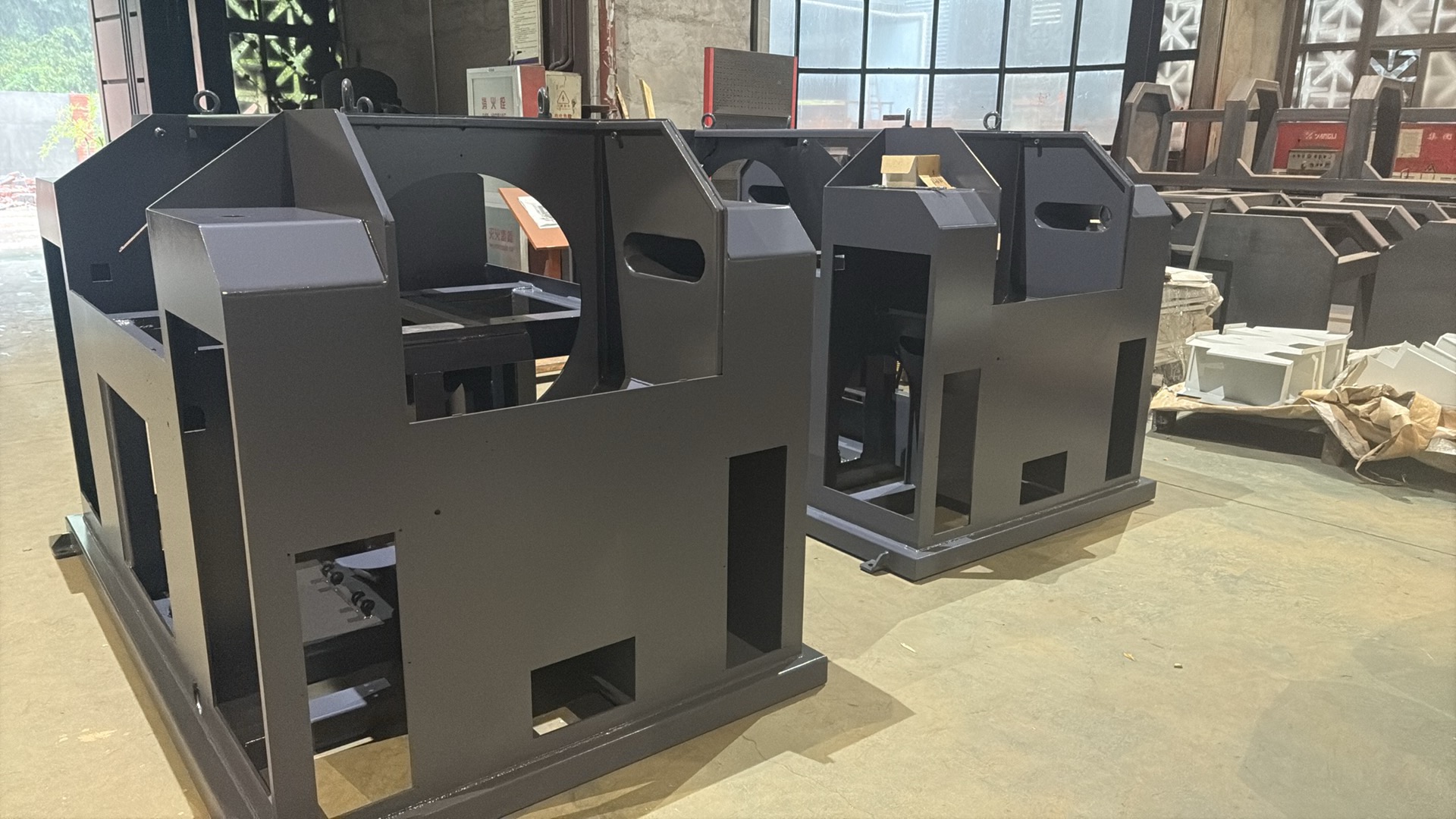
Sheet metal fabrication: the engineering guide
The chapters below are the ones that decide whether a sheet metal part is cheap or expensive, quick or slow, and whether the first article passes. They are written for the engineer preparing the drawing, and they are the same points our DFM review raises when a drawing arrives.
Gauge is a position in a table, not a thickness: 18 gauge is 1.214 mm as steel, 1.310 mm galvanised, 1.270 mm stainless and 1.024 mm as B&S aluminium. State millimetres on the drawing, with the tolerance. The conversion is on the sheet metal gauge chart.
The minimum inside radius scales with thickness, so a radius that forms cleanly in 1 mm sheet cracks in 2 mm. The flat pattern comes from a bend allowance with a K-factor that depends on the tooling and the material - we calculate it, then confirm it on the first part rather than trusting a table alone.
Most of a sheet metal drawing does not need a tolerance. The ones that decide whether the part assembles are hole position relative to a bend, the bend angle, the overall envelope, and - on welded frames - which face is the datum after welding. Everything else is general tolerance.
TIG, MIG and spot welding are sequenced to control distortion; rivet nuts, weld studs, standoffs and threaded inserts are inserted before finishing. The joint choice changes the drawing: the torch needs access, and the insert needs a clearance and a flat face to sit on.
Powder coating is applied in-house for parts that fit our booth, with an external line for oversize work; plating, passivation, anodising and phosphating are subcontracted and named on the quotation. Film thickness moves dimensions, so masked faces and pre-finish sizes are planned with the drawing. See typical Ra values by process and anodising compared with powder coating.
The drawing, the quantity and batch pattern, the finish, and the interfaces that must not move: what the part bolts to, which face is the datum, and whether it is a one-off, a prototype or a repeat programme. Send those four and the route - cut and bend, weld and finish, or a die - comes back with the quotation.
Related: deep drawing, progressive die stamping, tube bending and the engineering articles.
Send Your Drawing for a DFM Review
Upload your part drawing, quantity, material and target cost. Balford engineering will review manufacturability and route it through the correct process.