
Which Metal Stamping Process Fits Your Part?
Three main routes solve different geometry and volume requirements. Balford evaluates the complete part rather than forcing every design into one process.
Progressive Die Stamping
Best suited to repeat-production strip-fed parts with multiple operations that can be integrated into a coil-fed tooling sequence.
Explore Progressive Die Stamping → 02Deep Drawing
Best suited to cups, sleeves, shells and housings where material needs to be formed into depth or enclosed geometry.
Explore Deep Drawing → 03Precision Metal Stamping
Best suited to parts where feature position, edge condition, flatness or dimensional repeatability directly affects function.
Explore Precision Stamping →How We Choose the Stamping Route
An engineering reference for first orientation — the final route is confirmed by a drawing review.
| Requirement | Progressive Die | Deep Drawing | Precision Stamping |
|---|---|---|---|
| Multiple strip-fed operations | Strong fit | Limited / geometry-specific | Possible |
| Deep enclosed geometry | Limited / geometry-specific | Strong fit | Possible |
| High feature-position control | Strong | Drawing-specific | Strong |
| High repeat volume | Strong fit | Strong fit when tooling is justified | Strong fit |
| Seamless cup / shell geometry | Limited | Strong fit | Limited |
| Fine sheared edge | Possible | Usually not primary route | Strong with fine blanking |
| In-die tapping | Possible | Project-specific | Project-specific |
The right route depends on geometry, material, annual volume, tooling investment and downstream requirements — this matrix is engineering guidance, not an absolute rule.
What Is Metal Stamping?
The drawing drives the process. The same metal alloy can require a different stamping route depending on thickness, geometry, tolerances, forming depth, annual volume and downstream operations.
Custom Metal Stamping Built Around the Part
Balford starts with your drawing, material spec, demand forecast and critical-to-function dimensions. Engineering review works through blank development, forming sequence, tool access, burr direction, springback, inspection methods and any post-stamping joining or finishing operations. The goal is a production-ready process that protects functional datums, absorbs normal material variation and gives practical inspection points — tooling, press selection, feeding, lubrication and quality planning are treated as one integrated manufacturing system.
What We Review Before Tooling
The same factors are used when evaluating a drawing for tooling, inspection and production.
Part Geometry
Form depth, feature spacing, radii and drawing direction reviewed against the drawing.
Material & Thickness
Grade, temper, thickness and surface condition confirmed before tooling.
Annual Volume
Demand pattern weighed against tooling investment and process automation.
Critical-to-Function Dimensions
Function-driving controls separated from general manufacturing dimensions.
DFM Review Before Tooling
The team reviews bend relief, hole-to-edge distance, formed feature spacing, corner radii, drawing direction and accessible datums. Potential splitting, wrinkling, distortion, difficult trimming or unnecessary secondary work is identified early so that the drawing and process can be aligned before tooling release.
How Metal Stamping Tooling Is Selected
Tooling is planned around the required operations, material behavior and expected production pattern — with wear areas, replaceable components, scrap removal, feeding and mistake-proofing considered.
| Tooling Route | Best Fit |
|---|---|
| Progressive Die | Repeat strip-fed parts with multiple stations |
| Compound Die | Multiple operations within one press stroke |
| Transfer Die | Parts that need separate forming stations and workpiece transfer |
| Conventional / Single-Operation | Simpler geometry, lower tooling complexity or project-specific requirements |
Tooling selection is reviewed per drawing — see Progressive Die Stamping for the detailed tooling comparison.
Metal Stamping Process Options
Operations selected around the part rather than treated as a standard package.
Blanking
Separates the required profile from sheet or strip material.
Piercing
Creates holes or openings with controlled tool clearance.
Bending
Forms angles and flanges with controlled bend location.
Forming
Bends or reshapes material into functional features.
Drawing
Forms depth and enclosed geometry from flat material.
Embossing
Adds shallow relief or stiffening features.
Coining
Refines localized thickness, flatness or detail.
Fine Blanking
Produces smooth sheared edges for functional parts.
In-Die Tapping
Forms threads within the progressive sequence.
Secondary Operations Around the Stamped Part
Tapping, deburring, washing, heat treatment, plating, coating, welding or subassembly can be coordinated where required. The order of operations is reviewed because finishing buildup, heat input and handling can change dimensions, surface finish, fit, appearance or the tolerance stack after stamping.
Materials for Custom Metal Stamping
Material grade, temper, thickness and surface condition affect forming behavior and tool design.
Carbon & Low-Alloy Steels
Common for brackets, washers, retainers and structural parts; strength, springback and corrosion protection reviewed together.
Stainless Steels
Corrosion resistance with deliberate process planning for work hardening, galling and grain direction.
Aluminum Alloys
Weight and corrosion priorities; alloy and temper directly affect bend limits, marking and drawability.
Copper & Brass
Conductivity and appearance with surface protection and handling planned into the process.
Titanium & Special Alloys
Feasible for select applications after a full material and geometry review.
All Materials
Formability, springback, work hardening, burr, temper and surface condition all affect the route.
Applications for Custom Stamped Metal Parts
Where custom-stamped components are used across our production programs.
Automotive Components
Sensor housings, brackets, retainers, washers and formed parts that assemble consistently.
Sensor & Electrical Components
Sensor parts, terminals, shields and clips with controlled material and geometry.
Solenoid & Valve Components
Deep-drawn housings, sleeves, spring seats and magnetic or fluid-control components.
Industrial Equipment
Clips, covers, mounting parts and subcomponents produced to specific drawings.
Specialized Components
Selected precision parts with documented traceability and confidential handling, reviewed individually.
Washers & Shims
Flat precision parts with controlled tolerances across materials.
How We Control Metal Stamping Quality
A stable stamped part depends on decisions made before steel is cut — reviewed during quotation, tooling and sample approval.
Material Verification
Material grade, thickness and condition verified against the approved production specification.
Tool & Process Control
Tooling condition, feeding, setup and process stability monitored per the production plan.
In-Process Inspection
First-piece and in-process checks cover dimensions, visual condition and material requirements.
Final Inspection
Final checks verify the drawing; PPAP, IMDS, RoHS-related records and other customer documentation can be discussed when part of the project requirements.
Representative Metal Stamping Case Studies
Real parts, real materials, real manufacturing requirements — from progressive, deep drawing and precision programs.

Precision Stainless Steel Nut Washer
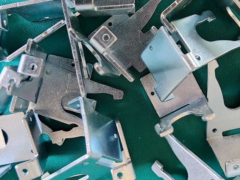
Stamped Metal Bracket
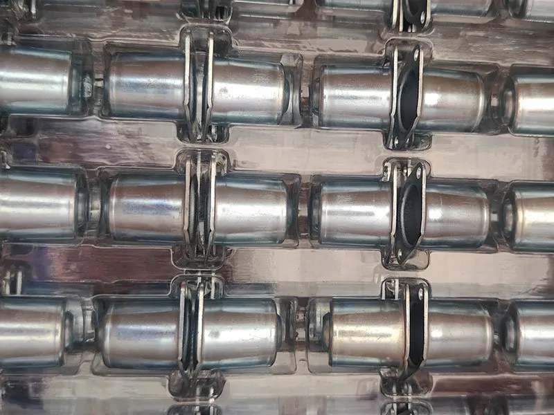
Spring Cup for Valve Application
From RFQ to Repeat Production
A complete quotation package includes a controlled 2D drawing, a 3D model when available, material grade and condition, expected order quantities, surface finish, functional requirements, and any special inspection or documentation needs.
Send the RFQ Package
Drawing, CAD model, material spec, target volume, finish and delivery schedule.
Engineering Review
Manufacturing route, critical features, tooling concept, secondary ops and open questions.
Tooling & Sampling
Approved tool plan developed; samples produced and dimensional or functional checks documented.
Approval & Production Release
Production released after sample approval with agreed in-process and final inspection controls.
Repeat Production
Controlled process maintained while engineering changes, tool maintenance and delivery are reviewed.
Metal Stamping FAQ
Answers based on drawing review because material, geometry and production volume drive what is practical.
Metal stamping uses dies and press equipment to cut, bend, form or draw sheet or strip metal into repeatable components. The appropriate tooling route depends on the part geometry, material, tolerance, production volume and downstream requirements.
Progressive stamping moves strip material through multiple stations to perform related operations, while deep drawing forms a blank into depth to create cups, sleeves, shells or housings. Some projects may combine both approaches when the geometry and production route allow it.
Consider progressive stamping when a part requires multiple operations in a repeat-production program and the material can remain attached to a strip carrier through the tooling sequence — see the Progressive Die Stamping capability page.
Deep drawing is the practical route for seamless cups, sleeves, shells and housings where a one-piece formed body is preferable to a welded or multi-piece assembly — see the Deep Drawing capability page.
Precision stamping applies when edge condition, feature position, flatness or dimensional repeatability directly affects assembly or function — see the Precision Metal Stamping capability page.
Carbon and low-alloy steels, stainless steels, aluminum, copper, brass and select special alloys are all practical candidates. Grade, temper, thickness and surface condition affect forming behavior and tool design — final capability is confirmed from the actual material specification.
Annual volume is one of the factors used to justify tooling investment and process automation. It is weighed together with part geometry, material, operation sequence and secondary operations — there is no fixed volume threshold.
There is no useful standard price because tooling complexity, material, part geometry, tolerances, annual volume, secondary operations and inspection requirements all affect project cost. Balford quotes from the actual drawing and production requirements.
Send the 2D drawing, 3D model when available, material grade, thickness, annual volume, critical tolerances, surface finish, secondary operations and any documentation requirements.
Confidential Project Review
Customer drawings and project details are handled as confidential manufacturing information. NDA requirements can be discussed before detailed files are exchanged, and project information is used only for quotation, engineering, quality and production activities tied to the authorized program.
Send Us Your Drawing
For a faster review, send: 2D drawing, 3D model, material grade, thickness, annual volume, critical tolerances, surface finish and secondary operations. Balford will review the production route and identify any technical questions before quoting.
Related Capabilities & Resources
Metal stamping connects to the full capability cluster, materials, applications, case studies and quality resources.
Related manufacturing capability: progressive die stamping, deep drawn metal stamping, precision metal stamping or in-house tooling design and build — all reviewed from the same drawing before quoting.
Once a part needs more than a couple of forming stages, transfer press stamping is usually the cheaper route than a bigger progressive die.
Commercial questions are answered here: tooling cost and lead time.
Capacity at a glance: press capacity up to 350 t · maximum deep draw diameter Ø250 mm · full machinery and inspection list.
Prototypes and pilot batches run on single-operation tooling rather than a strip — see low volume stamping and prototyping.