
Deep drawn stamping and progressive die stamping serve fundamentally different manufacturing needs. Deep drawing excels at producing seamless, hollow components with uniform wall thickness and depths exceeding part diameter. Progressive die stamping is optimized for high-volume production of flat or contoured parts with complex features formed in sequence. Process selection directly impacts part quality, tooling costs, scrap rates, and production efficiency. The key differentiator is part depth and geometry—deep parts require material flow, while progressive dies perform sequential operations on strip-fed material.
Deep drawn stamping is a metal forming process where a flat sheet metal blank is radially drawn into a die cavity by a punch, creating seamless, hollow parts. The defining characteristic of deep drawing is that the depth of the formed part exceeds its diameter.
The process occurs through multiple stages or “draw reductions” to prevent tearing or wrinkling. Each stage progressively works the material closer to final geometry while controlling thinning and work hardening. The metal flows like a viscous fluid, resulting in uniform wall thickness throughout the part.
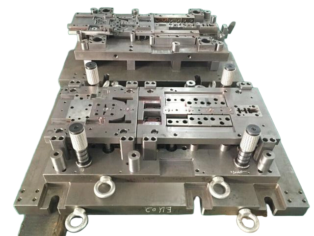
Seamless Construction: Produces parts with no weld joints, seams, or fastener points. This is critical for fluid transfer components, pressure vessels, and housings requiring structural integrity.
Uniform Wall Thickness: The material flow characteristics of deep drawing produce parts with consistent wall thickness and mechanical properties throughout.
Complex Geometries: Creates deep, hollow shapes with complex features that cannot be efficiently produced through other methods.
Work Hardening Benefits: Plastic deformation during drawing increases tensile strength, giving finished parts better strength-to-weight ratios than the flat sheet they originated from.
Smooth Surface Finish: The drawn surface typically exhibits fewer tool marks and interruptions compared to progressive stamping, making deep drawing ideal for visible parts and applications requiring cosmetic quality.
Higher Tooling Costs: Deep drawing dies are more complex and expensive to produce than progressive stamping tooling, particularly for multi-stage draws.
Slower Production Speeds: Deep drawing operates at moderate speeds compared to progressive stamping due to multiple forming stages and controlled material flow.
Material Constraints: Requires highly ductile materials with elongation above 30% and low yield-to-tensile strength ratios below 0.65. Not suitable for brittle metals or high-strength alloys without intermediate annealing.
Specialized Equipment: Requires presses and tooling configurations specific to deep drawing, limiting the number of factories capable of performing the process.
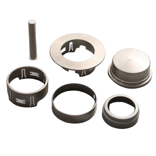
Progressive die stamping is a high-speed manufacturing process where a strip of metal is fed through multiple stations within a single tool. Each station performs one or more operations—blanking, piercing, bending, embossing, coining, or forming—until a finished part emerges at the final station, where it is cut free from the carrier strip.
The process relies on precise strip advancement, typically guided by pilots that engage previously pierced holes to ensure alignment within thousandths of an inch.
High-Speed Production: Capable of producing parts at speeds exceeding 800 parts per minute for simple geometries.
Cost Efficiency at Volume: Once tooling is amortized, per-part costs are significantly lower than deep drawing for compatible geometries.
Complex Feature Combinations: Multiple features—holes, bends, forms, and embossing—can be produced in a single tool, eliminating secondary operations.
Lower Tooling Investment: Progressive dies generally cost less than multi-stage deep draw tooling for parts with shallow features.
Consistent Quality: Automated strip guidance and in-die monitoring systems enable repeatable results across long production runs.
Depth Limitation: The general industry limit for progressive die drawing is approximately 1.5 times the part diameter. Beyond this ratio, the carrier strip connection starves the forming station of material, causing thinning, tearing, and distortion.
Carrier Tab Witness Marks: Each part carries small marks where it separated from the carrier strip. For decorative faces, these marks must be positioned away from view or require secondary finishing.
Station Marks: Multiple forming stations can leave visual witness marks on the part surface.
Material Restriction: Parts are formed while connected to the strip, limiting the ability to perform processes that require the part to leave the strip (beading, necking, flange curling, thread rolling).
Reduced Design Flexibility: Design changes typically require new tooling, adding cost and lead time compared to the iterative nature of deep drawing.
| Feature | Deep Drawn Stamping | Progressive Die Stamping |
|---|---|---|
| Part Depth | Exceeds part diameter; deep, hollow shapes | Shallow or contoured designs; typically depth < 1.5× diameter |
| Production Speed | Moderate (multiple draw stages) | High (up to 800+ parts/min) |
| Tooling Cost | High (complex dies, multi-stage) | Moderate to high (depends on feature count) |
| Wall Thickness | Uniform, consistent mechanical properties | Variable, may have thinning at bends |
| Material Suitability | Ductile, malleable metals (aluminum, stainless, copper) | Wide range, including harder metals |
| Seamless Construction | Yes—no joints or seams | No—features sequential forming |
| Surface Finish | Smooth, minimal tool marks | May have carrier tab marks, station marks |
| Application Fit | Housings, enclosures, fluid components, pressure vessels | Brackets, clips, connectors, multi-feature components |
| Scrap Rate | Lower when properly staged | Can be higher due to carrier strip waste |
| Design Flexibility | Greater for iterative changes | Limited after tooling is committed |
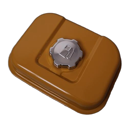
Automotive: Fuel tanks, EV battery housings, brake system components, structural parts exposed to pressure or vibration.
Medical Devices: Metal housings for surgical instruments, implantable device enclosures requiring corrosion resistance and smooth finishes.
Aerospace: Fuel system components, airframe parts, applications requiring strength-to-weight optimization.
Consumer Goods: Beverage cans, kitchen sinks, appliance housings requiring cosmetic finishes.
Fluid Systems: Hydraulic components, fluid transfer parts, pressure vessels.
Automotive: Brackets, clips, fasteners, multi-feature stamped components with stable, high annual usage.
Electronics: Connector shells, EMI shields, precision components for consumer electronics.
Industrial: Hardware, panels, components requiring piercing, bending, and forming in a single tool.
Aerospace: Structural brackets, standard hardware items.
Material Selection: Deep drawing requires materials with high anisotropy (r-value above 1.6) and elongation above 30%. Materials with low yield-to-tensile strength ratios (below 0.65) perform best.
Punch and Die Radii: For deep drawing, die entry radius should be 4 to 10 times material thickness to control material flow and stress concentration.
Draw Reduction Planning: Respect material limits for each draw stage. Aggressive reductions cause tearing; insufficient reductions increase cost through additional stages.
Lubrication Strategy: Deep drawing requires effective lubrication to reduce coefficient of friction from 0.15 to 0.05, lowering punch load requirements by up to 30%.
Tolerance Considerations: Progressive stamping can achieve tight tolerances, but springback and tool wear must be accounted for. Deep drawing delivers consistent dimensional accuracy but requires careful die design to manage thinning.
Industry Standards: Reference ISO 2768 for general tolerance guidance. Regulated industries (automotive, medical, aerospace) typically require specific quality management system certification.
Deep drawing is a metal forming process that produces seamless, hollow parts with depths exceeding their diameter by drawing material into a die cavity. Progressive stamping is a high-speed process where a strip of metal passes through multiple stations, each performing an operation, to form flat or contoured parts. The primary difference is part depth—deep drawing creates deep, hollow shapes while progressive stamping is for shallow or contoured designs.
Deep drawing is the preferred process for deep, cylindrical parts. The general rule is that if part depth exceeds approximately 1.5 times the diameter, a progressive die will struggle with tearing and distortion due to the carrier strip restricting material flow. Deep drawing allows the blank to move freely, pulling metal into the cavity through staged reductions.
The limiting draw ratio (LDR) is the maximum blank diameter to punch diameter ratio achievable in a single drawing operation without failure. For most ductile metals, LDR ranges from 1.8 to 2.3 in a single operation. Parts requiring deeper draws need multiple stages with intermediate annealing.
Deep drawing typically has higher initial tooling costs due to more complex dies and specialized equipment. However, for compatible geometries, deep drawing can produce parts more cost-effectively at production volumes when factors like scrap rate, secondary operations, and part performance are accounted for. Forcing deep parts through progressive stamping can cause 40% scrap rates, eroding any tooling savings.
Deep drawing requires highly ductile, malleable metals. Common materials include aluminum (1100, 3003), stainless steel (300 series), copper alloys, low-carbon steel, and certain titanium and nickel alloys. Materials should have elongation above 30% and low yield-to-tensile strength ratios.
Deep drawing generally yields smoother surface finishes with fewer tool marks, making it ideal for cosmetic applications like visible housings. Progressive stamping produces clean sheared edges but can leave carrier tab marks and station witness marks. For parts with decorative faces, the tab position must be planned away from visible areas or secondary finishing is required.
Progressive stamping is faster, capable of producing over 800 parts per minute for simple geometries. Deep drawing operates at moderate speeds—typically 15 to 40 strokes per minute—due to the multiple forming stages and controlled material flow required to prevent defects.
Stainless steel combines corrosion resistance, strength and durability across wet, chemical, high-temperature, low-temperature and high-pressure environments. These properties make it attractive for structural, wear-resistant and precision housing applications.
The same properties make stainless steel more demanding to deep draw than many conventional sheet materials.
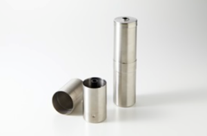
Stainless steel can harden rapidly under cold work. Local over-strain affects later piercing, machining and dimensional control, while high forming forces increase demands on die strength, alignment and wear resistance.
Draw ratios, radii, blank-holder force, lubrication and station sequence must be selected to control cracking and wrinkling while maintaining a uniform wall.
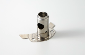
A successful stainless process may include fitting surfaces, pierced features and controlled edges in addition to the basic drawn form. Venting inside the tool is important where trapped air could affect the component. Edge finishing and final sizing must be planned from the beginning.
Balford has developed stainless drawing sequences that can avoid intermediate annealing for suitable materials and geometries, reducing handling while maintaining precision.
Tool design and manufacture are coordinated with the required material and geometry. Engineers calculate the number and order of forming stages and evaluate whether conversion from a welded or machined process can lower cost.
The development team verifies every stage through tool trials and measurement before approving the process for production.
Drawn stainless components are used in containers, housings, fittings and industrial assemblies where corrosion resistance and long service life matter. When considering a new design, early review of material grade, wall requirement, annual volume and functional surfaces helps identify the most economical route.
Local thickening is an integrated forming method that moves material into a selected area so one component can contain both thin and thick sections. The reinforced area can improve strength and durability without increasing the gauge of the entire blank.
The technique also gives designers more freedom to create functional transitions and curved forms that would be difficult to obtain through conventional stamping alone.
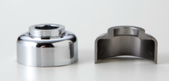
Balford developed a multi-stage process that locally increased a high-strength material to approximately twice its original sheet thickness while controlling buckling, folding and cracking. In the formed region, work hardening increased strength to about 1.5 times that of the starting material.
The original assembly used a stamped cup, a separate washer and welding. Forming the thickened feature directly into the cup converted the design into a single stamped component.
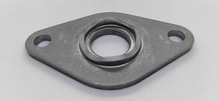
High-strength sheet has lower ductility and creates greater forming load than conventional steel. Dividing material movement across several calculated stages is essential to prevent fracture and unwanted folds.
Tooling simulation, die development and controlled tryout are used to establish a repeatable production window before volume manufacture.
Local thickening is most valuable when the current design carries extra gauge everywhere or joins several elements only to reinforce one location. Balford can review the assembly and assess whether a one-piece precision stamping can meet the same functional requirement.
High-quality sheared edges, close flatness and reduced secondary machining for precision parts.
Deep drawing is already one of the more demanding stamping processes. When the part combines non-cylindrical walls, openings, flanges and multiple forming directions, the finished geometry cannot be achieved by simply adding stations in an obvious order.
Tooling engineers work backward from the completed part to define how material must flow at every stage. The sequence, radii, draw depth and restraint must control stretch and compression without losing dimensional accuracy or uniformity.
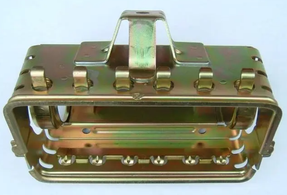
Balford combines multi-stage deep drawing with reverse-draw methods for difficult shapes. A part may first be formed deeply in the normal press direction, then redrawn in the opposite direction before a flange or final feature is formed.
This coordinated material movement enables geometries that would be difficult to produce with a single-direction process.
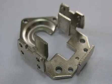
Complex aluminum parts can provide major weight savings; aluminum is approximately one-third the density of steel. This is useful in electric vehicles and other applications where every gram matters.
Aluminum also transfers heat quickly, is relatively soft and can adhere to tooling. Speed, cooling, lubrication, die material and surface condition all require careful control to avoid cracks, wrinkles and galling.
Balford reviews how many operations are necessary, in what order the geometry should be formed and whether a process conversion can reduce total cost. This development work continues through tool tryout and sample validation.
The engineering team evaluates cost, quality and function together. Rather than forcing a drawing into a standard route, the aim is to propose a process that fits the product requirement and is stable enough for production.