
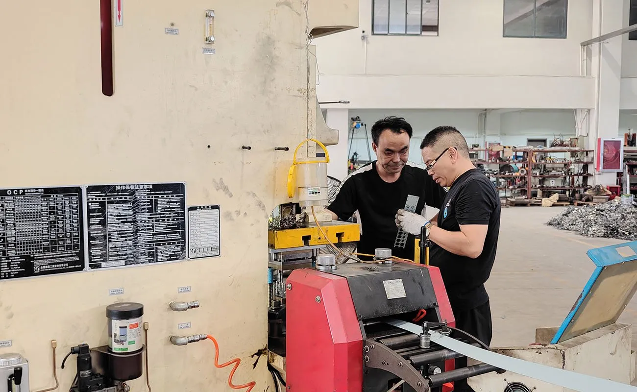
Precision Metal Stamping Services China
Precision Metal Stamping
Custom precision stamped parts, fine blanking and controlled forming for functional geometry, repeatable assembly and production quality.
Request for QuoteEngineering-Led Manufacturing
Precision Stamping for Function-Critical Metal Parts
Precision metal stamping combines purpose-built tooling, controlled press motion and drawing-specific inspection to produce parts where feature location, flatness, edge condition or formed geometry has a direct effect on function. Balford supports custom stamped components for automotive, electrical, industrial, medical and equipment applications from engineering review through repeat production.
The process may include blanking, piercing, bending, coining, embossing, drawing, slotting or fine blanking. These operations are selected around the part rather than treated as a standard package. For example, a clean functional edge may justify fine blanking, while a conventional blank followed by a calibrated secondary operation may be more practical for another design.
Balford has previously described precision work in the IT7 to IT9 range for suitable features. This is not applied as a blanket promise to every dimension. Actual capability depends on material, thickness, feature type, tooling route, datum strategy and measurement method, and is confirmed during project review and sampling.
Discuss Your Drawing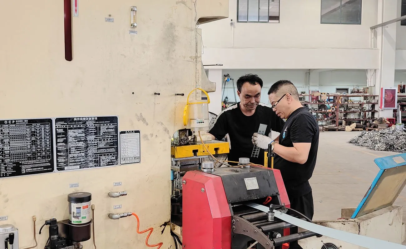
Process Options
Precision Stamping Process Options
The correct process balances functional requirements, edge quality, tooling investment and production volume.
Precision Progressive Stamping
Progressive stations can combine closely related blanking and forming operations while maintaining strip control. It is considered for repeat programs with multiple features and a stable material specification.
Learn MoreFine Blanking
Fine blanking uses controlled material support and tool conditions to produce a high proportion of smooth sheared edge on suitable parts. It can reduce downstream edge machining when the geometry, material and volume support the process.
Learn MoreCoining and Calibrating
Localized pressure can refine thickness, flatness, radii or functional details. Coining and calibration are evaluated with material flow, tool load and dimensional measurement in mind.
Learn MoreTechnical Comparison
When to Consider Precision Stamping
| Requirement | Precision stamping response | Alternative to compare | Decision point |
|---|---|---|---|
| Repeat feature position | Dedicated tooling locates related holes, edges and formed features | CNC machining or fabricated assembly | Volume, datum strategy and accumulated tolerance |
| Functional cut edge | Fine blanking or controlled shearing may improve edge condition | Blanking plus machining or grinding | Required smooth zone, burr limit and material |
| High part consistency | Controlled strip, tool guidance and in-process checks support repeat production | Manual fabrication | Quantity, change frequency and tooling economics |
| Complex formed detail | Coining, embossing or staged forming can integrate the feature | Secondary machining or assembly | Material strain, tool access and inspection |
| Thin or compact component | Precision tooling can combine small related features | Photo etching, laser cutting or machining | Material, edge quality, deformation and production scale |
Manufacturing Control
What Drives Precision and Edge Quality
Tight drawings do not become capable processes by inspection alone. The tooling, material, datums and measurement plan must support the requirement.
Datum and Tolerance Strategy
Functional datums should represent how the part locates in the assembly. Balford reviews position, profile, flatness and formed dimensions against those datums so gauges and inspection reports describe real part function.
Tool Guidance and Clearance
Punch-to-die relationship affects burr, edge condition, dimensional stability and tool wear. Clearance is selected for the specified material and feature, while die guidance and maintenance protect the relationship during repeat production.
Flatness and Distortion
Cutting force, residual stress, coining, forming and part ejection can influence flatness. Restraining, pressure control, calibration and handling may be evaluated where a flat interface is critical.
Measurement and Capability
Inspection equipment is selected for the feature and tolerance. First-article or sample reports, attribute gauges and production checks can be discussed. Capability expectations are defined for agreed critical dimensions rather than inferred from a general page claim.
Material Planning
Materials, Finishes and Secondary Operations
Precision parts often continue through plating, heat treatment or assembly. These downstream operations must be included in the tolerance and surface plan.
Carbon and spring steels
Used for clips, washers, shims and functional parts; hardness, heat treatment and coating can change flatness or dimensions.
Stainless steels
Selected for corrosion resistance and strength; work hardening, burr, tool wear and surface protection require attention.
Copper and copper alloys
Useful for conductive or spring features; grain direction, plating, cleanliness and handling may affect performance.
Aluminum alloys
Support low-mass parts and corrosion resistance; temper influences deformation, burr and springback.
Plating, coating and assembly
Finish thickness, masking, hydrogen-related concerns, press-fit features and mating parts are reviewed before production release.
Application Experience
Precision Stamped Part Applications
Automotive and Sensor Systems
Shims, retainers, washers, housings and functional components that depend on repeatable interfaces and controlled production.
Electrical and Electronic Products
Terminals, shields, conductive parts and compact hardware requiring controlled material, geometry and surface condition.
Industrial Equipment
Locking parts, guides, brackets, wear components and assembly hardware made to customer-specific drawings.
Medical and Specialized Products
Selected precision parts with material, inspection, cleanliness and confidentiality requirements defined by the project.
Evidence and Resources
Precision Stamping Examples
These examples and technical resources explain how drawing requirements are translated into a practical production plan.
65Mn Spring Steel Shim
A spring-steel shim case where profile, flatness and edge condition influence assembly. Material condition and downstream treatment must be considered with the stamping plan.
Learn MoreStainless Steel Nut Washer
A compact stamped component showing how related features and formed geometry can be produced in a controlled tooling sequence and checked from functional datums.
Learn MoreCopper Base Plate
A copper component where material handling, flatness, surface condition and dimensional interfaces require coordination across stamping and final inspection.
Learn MoreProject Preparation
Building a Capable Precision Stamping Program
The quotation stage should separate dimensions that are essential to function from those that can follow an appropriate general tolerance. This prevents unnecessary tooling and inspection cost while protecting assembly performance. Balford can review the drawing and point out features that need clearer datums, burr direction or surface requirements.
During sampling, the customer and Balford review actual parts against the agreed measurement plan. Where a feature is sensitive to material or tool condition, the control plan can include a practical production check. The approved sample and controlled drawing then become the reference for repeat supply.
Engineering changes should be communicated before a new revision is ordered. A small change in hole position, radius, material temper or coating can alter tool steel, pilots, gauges or assembly fit. Formal review protects both quality and delivery.
How to Start Working
A Controlled Project Workflow
Define critical features
Share the drawing, datum system, material, finish, quantity and functional priorities.
Select the process route
Compare progressive stamping, fine blanking, coining and secondary operations against the requirement.
Develop tooling and gauges
Create the approved tool plan and inspection approach for critical features.
Sample and verify
Measure samples, review edge and surface condition, confirm fit and close corrective actions.
Release repeat production
Control setup, material, tool maintenance, inspection and engineering revisions.
Frequently Asked Questions
Precision Metal Stamping FAQ
Answers are intentionally based on drawing review because material, geometry and production volume change what is practical.
Ask an EngineerWhat makes precision stamping different from conventional stamping?
Precision stamping places greater emphasis on tool guidance, datum relationships, edge condition, flatness and measurement of function-critical features. The process may use progressive tooling, fine blanking, coining or calibration, depending on the drawing and production requirement.
Can Balford hold IT7 to IT9 accuracy?
Balford has described IT7 to IT9 capability for suitable precision-stamped features, but it is not a universal tolerance for every part. Material, geometry, feature type, datum distance, tooling and measurement method must be reviewed. Drawing-specific capability is confirmed during quotation and sampling.
When should fine blanking be selected?
Fine blanking is considered when a part needs a high proportion of smooth sheared edge, improved flatness or a functional edge that might otherwise require machining. Geometry, material, thickness, volume and tooling economics determine whether it is the most suitable route.
Can heat treatment or plating be included?
Yes, these operations can be coordinated when specified. Their effects on hardness, distortion, coating thickness, surface condition and hydrogen-related risk must be included in the process and inspection plan.
How is burr direction controlled?
Burr direction is established from punch and die orientation and should be marked where it affects assembly, sealing, safety or appearance. Balford reviews the desired direction with strip layout, part ejection and downstream operations.
What files are needed for a precision stamping RFQ?
Provide a controlled 2D drawing, 3D model if available, material and temper, finish, annual and batch quantities, critical dimensions, edge or flatness requirements, inspection documentation and the intended assembly context.
Secure Project Review
Send Balford Your Drawing
Share the latest revision, material, quantity, finish and functional priorities. NDA requirements can be discussed before detailed project files are exchanged.
Request for Quote