
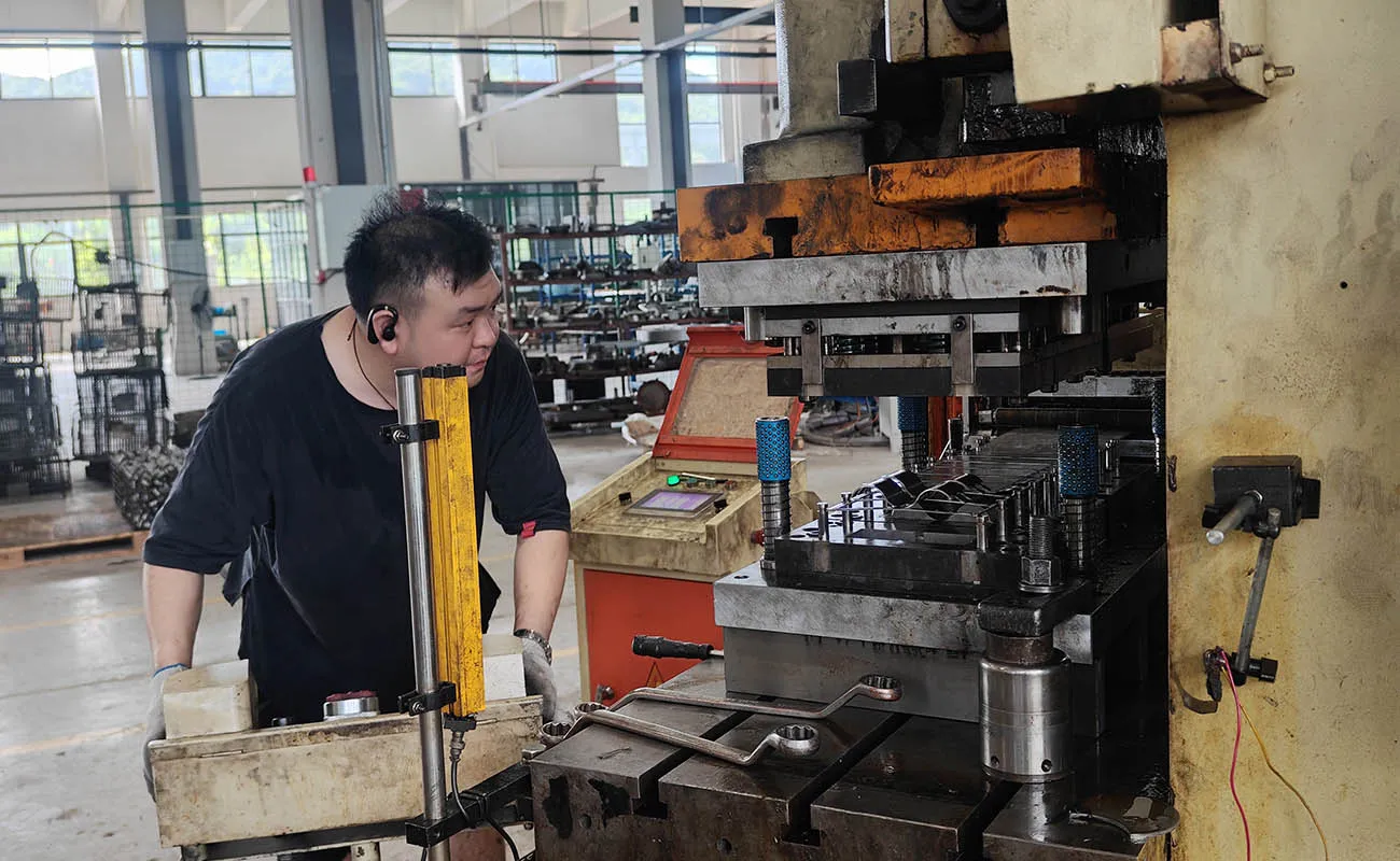
Deep Draw Stamping Services China
Deep Draw Metal Stamping
Custom deep-drawn housings, sleeves, cups and bushes with engineering focused on material flow, wall condition and repeatable production.
Request for QuoteEngineering-Led Manufacturing
Engineering Seamless Deep-Drawn Metal Parts
Deep drawing converts a flat metal blank into a three-dimensional cup, bush, sleeve or housing by drawing material into a die cavity. The process can remove weld seams, reduce part count and create an efficient production route for components that need depth, controlled walls and a clean external form. Successful deep drawing depends on the interaction between material properties, blank shape, draw stages, punch and die radii, lubrication, blank-holder force and trimming.
Balford supports single-operation and multi-stage deep drawing as well as progressive deep-draw concepts when the geometry and production requirement are suitable. Engineering review begins with the finished component and works backward through intermediate forms. This makes it possible to identify where material must flow, where thinning or wrinkling may occur and where redrawing, ironing, annealing or another secondary operation may need evaluation.
Typical applications include solenoid and valve housings, sensor shells, motor covers, magnetic isolation sleeves, spring cups and other seamless formed components. Materials may include stainless steel, carbon steel, aluminum, copper, brass, titanium or other specified alloys, subject to a drawing and material review.
Discuss Your Drawing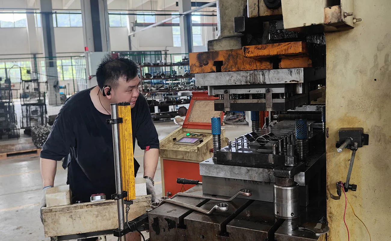
Process Options
Deep Drawing Process Options
The final route is selected from part depth, diameter or width, wall requirement, material behavior and production volume.
Conventional Deep Drawing
A blank is drawn through one or more controlled stages to create a cup or shell. The blank shape and draw sequence are developed to balance material flow and reduce splitting, wrinkling or excessive earing.
Learn MoreProgressive Deep Drawing
Drawing and related operations can be distributed across progressive stations for suitable repeat programs. Strip carrier design, feed stability and stage-to-stage material control are critical to protecting the formed component.
Learn MoreRedrawing and Ironing
Additional drawing or ironing may be evaluated where greater depth, controlled wall condition or a refined diameter is required. These operations are not assumed automatically; they are selected only after reviewing geometry and material response.
Learn MoreTechnical Comparison
Technical Factors Reviewed for Deep-Drawn Parts
| Design factor | Why it matters | How it is reviewed | Project output |
|---|---|---|---|
| Part depth and opening size | Influence the severity and number of draw stages | Finished geometry, intermediate forms and material behavior | Proposed draw sequence and tooling concept |
| Corner and bottom radii | Affect material flow, thinning and the risk of splitting | Functional need versus formability and tool access | Recommended production radius or controlled secondary feature |
| Wall condition | Thinning, thickening and local strain may affect function | Section requirements, material model and sample measurement | Drawing-specific inspection plan |
| Flange, trim and edge | Excess material and trim direction affect final geometry | Blank development, draw beads, trimming access and burr direction | Defined trim strategy and finished datum |
| Material grade and temper | Strength, ductility and work hardening change the process window | Actual specification, certification need and forming history | Approved material and change-control requirement |
Manufacturing Control
Controlling Common Deep Drawing Risks
Deep drawing defects are usually connected. A change that reduces wrinkling can increase thinning, while a smaller radius can raise the risk of cracking. The process is balanced around the functional drawing.
Thinning and Splitting
Material strain is concentrated around radii and transition zones. Appropriate radii, draw stages, lubrication and material condition help distribute strain. Critical wall sections can be measured during sampling so the customer and supplier agree on a practical control method.
Wrinkling and Earing
Blank-holder control, blank shape, anisotropy and draw-bead strategy influence wrinkles and uneven edge height. Trimming allowance and grain-related behavior are considered before the final blank and tooling are released.
Sharp Corners and Local Features
Very small radii or sharp functional corners may require a staged operation such as controlled extrusion, coining or localized forming. Balford reviews whether the feature is truly functional and proposes a route that protects the surrounding wall.
Springback and Dimensional Stability
Material strength, work hardening and residual stress can change the part after it leaves the tool or after trimming. Tool compensation, restrike operations and datum-based inspection may be used when the geometry requires additional control.
Material Planning
Deep Drawing Materials and Selection Notes
The material name alone is not enough. Grade, temper, thickness, surface and lot consistency all affect drawability and should be defined before tooling approval.
Stainless steel
Corrosion-resistant housings and sleeves; work hardening, galling, lubrication and intermediate strain must be considered.
Low-carbon steel
A practical choice for many formed housings and cups; coating or post-finish requirements should be defined with the material.
Aluminum
Low weight and corrosion resistance; alloy and temper influence earing, surface marking, tearing and springback.
Copper and brass
Good formability for selected conductive or appearance-related parts; surface protection and material cost require careful handling.
Titanium and special alloys
Possible for qualified projects, but the process window, springback and tooling demands require specific engineering validation.
Application Experience
Where Deep-Drawn Components Are Used
Solenoid and Valve Components
Seamless housings, sleeves and spring-related parts for fluid or magnetic systems where cleanliness, wall integrity and controlled geometry matter.
Automotive Sensors and Motors
Sensor shells, motor covers and formed housings produced for repeat fit, environmental protection and downstream assembly.
Medical and Specialized Devices
Selected cups and enclosures requiring traceable material, defined inspection and confidential project handling.
Industrial and Aerospace Supply Chains
Application-specific shells and housings in controlled materials, subject to drawing, documentation and qualification requirements.
Evidence and Resources
Selected Deep Drawing Case Summaries
These examples and technical resources explain how drawing requirements are translated into a practical production plan.
ABS Wheel Speed Sensor Housing
A stainless steel housing application where the deep-drawn form protects the sensor assembly. Material flow, wall condition and final fit are reviewed together rather than as isolated dimensions.
Learn MoreHydraulic Cartridge Valve Housing
A valve housing example that demonstrates the value of a seamless formed body. Drawing depth, open-end trimming and functional interfaces influence the complete tooling sequence.
Learn MoreThin-Wall Aluminum Tube
A thin-wall aluminum example where alloy condition, drawing stages and handling must protect the wall and surface through forming, trimming and inspection.
Learn MoreProject Preparation
Developing a Reliable Deep Draw Process
The first technical discussion should identify which dimensions drive sealing, guidance, magnetic performance, assembly or appearance. This allows Balford to establish useful datums and avoid applying the same tight tolerance to every surface. A controlled part is easier to manufacture when inspection points reflect function.
For difficult materials or deeper forms, sampling is used to compare the actual part with the predicted process. Wall sections, edge condition, roundness, profile and functional fit can be reviewed according to the drawing. Any tooling adjustment is documented before production approval.
Balford can also review related operations such as piercing after drawing, trimming, ironing, washing, heat treatment, surface treatment and assembly. The order matters because cutting or finishing can release stress, add coating thickness or change the surface condition of the drawn part.
How to Start Working
A Controlled Project Workflow
Drawing and material review
Confirm functional datums, material grade and condition, depth, radii, wall requirements, quantity and finish.
Process and blank development
Plan blank geometry, drawing direction, intermediate stages, restrike, trim and any secondary operations.
Tooling and sample validation
Produce samples and evaluate the agreed dimensions, wall sections, appearance and functional fit.
Customer approval
Close open items, document approved samples and release the controlled process for repeat production.
Production control
Use defined setup, material and inspection requirements while managing tool maintenance and engineering changes.
Frequently Asked Questions
Deep Draw Metal Stamping FAQ
Answers are intentionally based on drawing review because material, geometry and production volume change what is practical.
Ask an EngineerWhat is the maximum deep draw ratio Balford can support?
There is no responsible single maximum for every part. Draw severity depends on material grade and condition, sheet thickness, blank geometry, part shape, radii, wall requirements and whether multiple draw stages are allowed. Balford evaluates the actual drawing and proposes a validated sequence before committing to capability.
Can Balford produce progressive deep-drawn parts?
Yes, progressive deep drawing can be evaluated for suitable geometry and repeat production. The strip carrier, feed pitch, number of draw stages, material movement and downstream trimming must all be reviewed to determine whether it is the best route.
How is wall thinning controlled?
Wall condition is managed through blank design, radii, draw sequence, lubrication, holder pressure and, where appropriate, ironing or restrike operations. Critical wall locations and the measurement method should be defined on the drawing or control plan.
Can deep drawing form sharp internal or external corners?
Sharp functional corners may require a staged operation such as coining, local extrusion or a secondary forming step. The team reviews the functional need, surrounding material strain and inspection method before recommending a process.
Which materials are suitable for deep drawing?
Common candidates include low-carbon steel, stainless steel, aluminum, copper and brass. Titanium and other special alloys may be possible after review. Grade, temper, thickness and surface condition are more important than the broad material family alone.
What should be included in an RFQ for a deep-drawn part?
Send the controlled drawing and model, material specification, quantity, finish, critical dimensions, wall or section requirements, functional tests and any traceability or documentation needs. Existing samples or assembly context can also help explain the functional priorities.
Secure Project Review
Send Balford Your Drawing
Share the latest revision, material, quantity, finish and functional priorities. NDA requirements can be discussed before detailed project files are exchanged.
Request for Quote