
Drawing is a commonly used die processing method in the manufacturing industry. In the drawing process, the drawing die is an indispensable processing tool. The drawing die has a significant impact on drawing quality and can easily lead to waste, which is why many people pay close attention to drawing dies. This is because drawing dies not only require consideration of many factors, but more importantly, they often cannot achieve the desired shape in a single trial run during die tryout. Multiple rounds of die correction are usually needed to achieve the ideal result. Therefore, accumulating experience in practice is highly beneficial to the design of drawing dies. So, what are the factors that affect the die processing of drawn parts? Below, the editors of Zhejiang Baifudu Electromechanical will take you through an in-depth understanding.
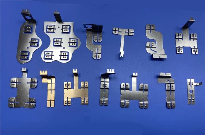
1. Material: Good material is half the battle. Material cannot be overlooked in drawing. Cold-rolled steel sheets are mainly made of 08Al, 08, 08F, 10, 15, and 20 steel, among which 08 steel is the most widely used and is divided into rimmed steel and killed steel. Rimmed steel is low in price and has good surface quality, but it has severe segregation and a tendency toward strain aging. It is not suitable for parts requiring high stamping performance and strict appearance requirements.
2. Determination of blank size: The blank diameter of simple rotary drawn parts does not thin during the drawing process. Although the material thickness changes, it remains essentially very close to the original thickness. It can be calculated based on the principle that the blank area equals the drawn part area (if trimming is required, trimming allowance must be added. However, the shape and process of drawn parts are often complex, and sometimes thinning and drawing occur. Although many 3D software programs can calculate material, their accuracy cannot reach 100% of the requirement.
Solution: Material testing. A product component should go through multiple processes, and the first process is usually the material transfer process.
First, perform material calculation to gain a general understanding of the blank shape and size, so as to determine the overall dimensions of the material transfer die. After the die design is completed, do not machine the punch and die dimensions of the material transfer die. First, use wire cutting to process the blank (when the blank is large, a milling machine can be used for milling, followed by repair). After repeated trial runs of the subsequent drawing processes, the dimensions of the feed transfer die are finally determined.
3. Drawing coefficient m is one of the main process parameters in drawing process calculations and is commonly used to determine the drawing sequence and number of drawing operations. Many factors affect the drawing coefficient m, including material properties, relative material thickness, drawing method (whether or not a blank holder is used), number of drawing operations, drawing speed, and punch and die corner radii. The calculation and selection principles of the drawing coefficient m are key points introduced in various stamping manuals, including calculation, table lookup, calculation, and many other methods.
Relative material thickness. Drawing method (whether or not a blank holder is used). During die correction, the number of drawing operations is not easy to adjust, so be careful! When selecting the drawing coefficient m, it is best to have a colleague review it. Apply lubricating oil on the die or place a thin film bag on the sheet.
4. When cracking occurs during drawing, apply lubricating oil on the die (not on the punch) and cover the die with a plastic film of 0.013-0.018 mm.
5. During the drawing process, cold plastic deformation causes cold hardening of the part, reducing plasticity and increasing deformation resistance and hardness. If the die design is unreasonable, intermediate annealing is required to soften the metal and restore plasticity. Note: In general processes, annealing is not necessary. After all, to increase cost, choosing to add processes and increase annealing amount should be used with caution! Annealing generally uses low-temperature annealing, i.e., recrystallization annealing.
Two points should be noted during the annealing process: decarburization and oxidation. This mainly concerns oxidation. Oxidized scale has two hazards: it thins the effective thickness of the workpiece and increases die wear. When company conditions are not met, ordinary annealing is generally used. To reduce the generation of oxidized scale, the furnace should be filled as much as possible during annealing. I have also adopted the soil method: 1. The workpiece can be mixed with other workpieces (premise: annealing process parameters should be basically the same) 2. Place the workpiece in an iron box for welding, then install it in an electric furnace. To eliminate oxidized scale, the furnace should be filled as much as possible during annealing.
When company conditions are met, nitrogen furnace annealing, also known as bright annealing, can be adopted. On close inspection, its color is almost identical to that before annealing. When there is no other way to address cold-hardened metal or cracks occurring during die tryout, an intermediate annealing process should be added.
The above covers die processing for drawn parts. When diagnosing the causes of cracks in drawn part processing, the following reference can be used: cracks caused by poor material quality are mostly jagged or irregular in shape, while cracks generated by process tooling are generally more uniform. To ensure wear resistance and prevent drawing scratches, the punch, die, and blank holder must be hardened, and hard chrome plating can be applied if necessary. It is hoped that the above content will be helpful to readers.