
Short answer: A good deep-drawing part is a closed or open shell whose wall has to stay continuous, and it stops being one when the depth-to-diameter ratio exceeds what the material can take in the stages the volume can pay for. Zhejiang Balford Mechatronics Co., Ltd. (balford.net) deep draws steel, stainless, aluminium, copper and brass up to Ø250 mm on presses from 25 t to 350 t, ironing and annealing where the wall or depth needs it.
Balford deep draws DC04 and pure iron (the DT4 series) for solenoid valve housings, stainless steel for sensor housings, and brass, copper and aluminium, on presses from 25 t to 350 t with a maximum deep draw diameter of Ø250 mm. Where a controlled wall is required the part is ironed, and tooling can be single-operation, progressive or transfer — all designed and built in the in-house tool room.
Is Deep Drawing Right for Your Part?
Deep drawing converts a flat metal blank into a three-dimensional cup, shell, sleeve or housing by drawing material into a die cavity. The process can remove weld seams, reduce part count and create an efficient production route for components that need depth, controlled walls and a clean external form. Start with the four checks below.
Deep Parts
For cups, sleeves, shells and housings with meaningful depth.
Seamless Form
Useful when a one-piece formed body is preferable to a welded assembly.
Repeat Production
Best suited to repeat production where tooling cost can be spread over volume.
Controlled Wall Geometry
Suitable where wall condition, diameter and depth must be managed together.
What We Make with Deep Drawing
Typical part families produced through our deep drawing programs — each links to the relevant application page.
Sensor Housings
Deep-drawn stainless steel or aluminum housings for pressure, temperature and wheel-speed sensor assemblies.
Solenoid Valve Housings
Seamless housings, sleeves and spring-related parts for fluid or magnetic systems.
Magnetic Sleeves
Thin-wall drawn sleeves with controlled wall thickness for magnetic isolation and rotor protection.
Motor Covers
Drawn motor shells and covers built for repeat fit, sealing and smooth downstream assembly.
Spring Cups
Drawn cups and retainers carrying spring preload with controlled depth and radii.
Deep-Drawn Cups & Shells
Custom cups, shells and housings across our application range — review your drawing for the practical route.
Deep Drawing Process Options
We select the final route based on part depth, diameter or width, wall requirements, material behavior and production volume.
Conventional Deep Drawing
A blank is drawn through one or more controlled stages to form a cup or shell. The blank shape and draw sequence are developed to balance material flow and minimize splitting, wrinkling or excessive earing.
BEST FOR- Prototype to repeat production
- Cups, housings, sleeves and shells
- Draw depth, blank geometry, material behavior and draw sequence
Progressive Deep Drawing
For suitable repeat programs, drawing and related operations are distributed across progressive stations. Strip carrier design, feed stability and stage-to-stage material control are critical to protecting the formed component. Best for repeat production where integrated strip-fed operations can justify progressive tooling.
RELATEDRedrawing & Ironing
Used when part depth, wall condition or diameter requirements cannot be achieved in a single draw. These operations are never assumed automatically — they are selected after a full review of geometry and material response.
RELATED- Deep drawing
- Ironing
- Annealing
- Restrike
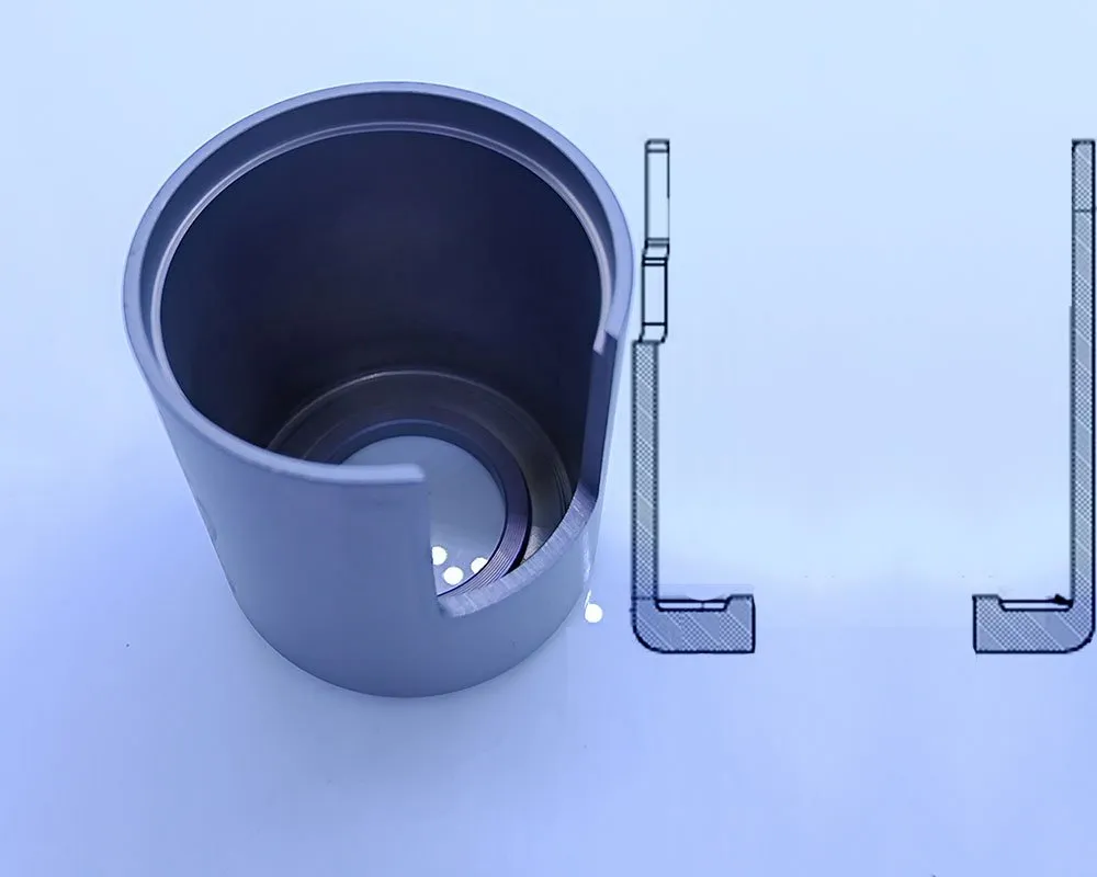
Deep Drawing Is a Material-Flow Problem
The result depends on how the material moves through each stage — not just the press tonnage. Blank geometry, material grade, thickness, radii, lubrication, blank-holder force and draw sequence all interact. Draw severity depends on part diameter, depth, blank size, material grade and temper, thickness, radii and the number of drawing stages available — there is no single maximum that fits every part.
Technical Factors We Review
Every deep-drawn part is reviewed against the same technical factors before tooling and quotation.
| Design Factor | Why It Matters | How It Is Reviewed | Project Output |
|---|---|---|---|
| Part depth and opening size | Drive the number and severity of draw stages required | Finished geometry, intermediate forms, and material behavior | Proposed draw sequence and tooling concept |
| Corner and bottom radii | Control material flow, thinning, and splitting risk | Functional need versus formability and tool access | Recommended production radius or controlled secondary feature |
| Wall condition | Thinning, thickening, and local strain can affect function | Section requirements, material model, and sample measurement | Drawing-specific inspection plan |
| Flange, trim, and edge | Excess material and trim direction affect final geometry | Blank development, draw beads, trimming access, and burr direction | Defined trim strategy and finished datum |
| Material grade and temper | Strength, ductility, and work hardening shift the process window | Actual specification, certification needs, and forming history | Approved material and change-control requirement |
These are the same factors we use when reviewing a drawing before tooling and quotation.
Common Deep Drawing Defects and How They Are Controlled
Deep drawing defects are typically interrelated — reducing wrinkling can increase thinning, and a tighter radius raises cracking risk. The process is balanced around the functional drawing.
Thinning and Splitting
Strain concentrates around radii and transition zones. Proper radii, draw stages, lubrication and material condition help distribute strain. Critical wall sections are measured during sampling.
CONTROL LEVERS- Blank design
- Draw radii
- Draw stages
- Lubrication
- Material condition
Wrinkling and Earing
Blank-holder force, blank shape, anisotropy and draw-bead strategy affect wrinkles and uneven edge height. Trimming allowance and grain behavior are considered before finalizing the blank and tooling.
CONTROL LEVERS- Blank-holder force
- Blank shape
- Anisotropy
- Draw-bead strategy
- Trim allowance
Sharp Corners and Local Features
Very small radii or sharp functional corners may require staged operations like controlled extrusion, coining or localized forming. Balford checks whether the feature is truly functional and proposes a route that protects the surrounding wall.
CONTROL LEVERS- Staged operations
- Coining / extrusion
- Localized forming
Springback and Dimensional Stability
Material strength, work hardening and residual stress can alter the part after it leaves the tool or after trimming. Tool compensation, restrike operations and datum-based inspection are used when geometry demands tighter control.
CONTROL LEVERS- Tool compensation
- Restrike
- Datum-based inspection
Deep Drawing Materials and Selection Notes
Specifying just the material name will not cut it. Grade, temper, thickness, surface condition and lot-to-lot consistency all directly impact drawability — and are confirmed before tooling is approved.
Stainless Steel
Good for corrosion-resistant housings and sleeves; work hardening, galling, lubrication and intermediate annealing may affect the draw sequence.
Low-Carbon Steel
A solid, practical choice for most formed housings and cups; define coating or post-finish requirements alongside the material spec.
Aluminum
Lightweight and corrosion-resistant; alloy and temper drive earing, surface marking, tearing and springback.
Copper & Brass
Formable options for conductive or cosmetic parts; surface protection and material cost need careful handling.
Titanium & Special Alloys
Possible for qualified projects, but the process window is tight — springback and tooling wear demand real engineering validation.
All Materials
Grade, temper, thickness, surface condition and lot-to-lot consistency all impact drawability — review before tooling.
Where Deep-Drawn Parts Are Used
Application experience across solenoid and valve components, automotive sensors and motors, and industrial components.
Solenoid & Valve Housings
Seamless housings, sleeves and spring-related parts for fluid or magnetic systems where cleanliness, wall integrity and controlled geometry are non-negotiable.
Automotive Sensor & Motor Housings
Sensor shells, motor covers and formed housings built for repeat fit, environmental sealing and smooth downstream assembly.
Magnetic Sleeves
Thin-wall drawn sleeves where wall condition and magnetic-circuit geometry must be managed together.
Industrial Components
Application-specific shells and housings in controlled materials, subject to full drawing, documentation and qualification requirements.
Spring Cups & Retainers
Drawn parts carrying spring preload with controlled depth, radii and seal faces.
Motor Covers & End Caps
Drawn end caps and covers with dimensional consistency for automated assembly.
Selected Deep Drawing Case Studies
These examples show how we turn drawing requirements into a workable production plan — not just on paper, but on the floor.

ABS Wheel Speed Sensor Housing
Hydraulic Cartridge Valve Housing

Thin-Wall Aluminum Tube
How We Develop a Deep-Drawn Part
The first engineering review pins down which dimensions actually control sealing, guidance, magnetic performance, assembly or appearance — so meaningful datums are set and the same tight tolerance is not applied to every surface. Samples are validated against the predicted process before production sign-off.
Drawing, Material & Function Review
We confirm functional datums, material grade and temper, draw depth, radii, wall requirements, annual quantity and surface finish.
Blank & Draw Sequence Development
We plan blank geometry, draw direction, intermediate stages, restrike, trim and any secondary operations needed.
Tooling & Sample Validation
We produce samples and verify agreed dimensions, wall sections, appearance and functional fit against the drawing.
Customer Approval
We close out open items, document approved samples and lock the controlled process for repeat production.
Controlled Production
We follow defined setup, material and inspection requirements while managing tool maintenance and engineering changes.
Deep Drawing Process Envelope
These are the limits we quote against. Geometry outside them is reviewed case by case before we accept it, and we tell you when a part is not a candidate rather than quoting it anyway.
| Parameter | What Balford works to |
|---|---|
| Maximum press tonnage | 350 t |
| Maximum draw diameter | Ø250 mm |
| Tooling | Designed and built in our own tool room — only slow-wire EDM is subcontracted |
| Materials | Stainless steel, carbon steel, aluminium, copper, brass and selected special alloys |
| Secondary operations | CNC turning and milling, wire EDM, deburring and controlled cleaning |
| Outsourced operations | Production heat treatment (quenching, tempering, annealing, demagnetising) and surface finishing such as electropolishing and passivation |
| Inspection equipment | 2.5D optical projector, 3D scanner, portable roughness tester, Rockwell hardness tester, salt-spray tester, digital height gauge, micrometres and bore micrometres, internal callipers, full go/no-go gauge sets, flash measuring instrument and concentricity gauge |
| Documentation | First article inspection and PPAP Level 3 packages |
If your part sits outside this envelope, tell us the requirement anyway — we will say whether it is achievable, and where it is not.
See deep drawing running
A stainless steel housing and a drawn bushing, filmed on the line that makes them.
Deep Drawing Engineering Guide
This is the working version of the list we go through when a drawing arrives: the numbers that decide whether a part can be drawn in one hit, in three, or not at all. It is written for the engineer who has to sign the drawing, not for a brochure.
Chapter 1 — Draw ratio: how many stages a part needs
The draw ratio is the blank diameter divided by the punch diameter for that stage. Exceed it and the part tears at the punch nose no matter how good the lubrication is. First-stage ratios we work to:
| Material | First-stage draw ratio | Note |
|---|---|---|
| Low carbon steel (DC01–DC04) | 1.8 – 2.0 | DC04 for the deeper draws; DC01 needs more stages |
| Stainless steel (304, 430) | 1.6 – 1.8 | Higher work hardening, so more stages and more annealing |
| Pure iron (DT4E / DC04 iron grades) | 1.8 – 2.0 | Good ductility, but watch the wall on the second stage |
Redrawing stages are progressively shallower than the first. Copper and aluminium parts are reviewed individually, because the alloy and temper move the limit more than the family does. See also how the maximum draw ratio is calculated.
Chapter 2 — Die clearance
Clearance is quoted per side, as a multiple of the sheet thickness t. Too tight and the wall is scored and the tool wears; too loose and the part wrinkles and the wall thins unevenly.
| Material | Clearance per side |
|---|---|
| Steel | 1.1 – 1.3 t |
| Aluminium | 1.0 – 1.2 t |
| Stainless steel | 1.2 – 1.4 t |
Chapter 3 — Blank size before you cut anything
For a cylindrical cup with diameter d and height h, the starting blank diameter is approximately √(d² + 4dh). It is an estimate, not a substitute for the die trial: the blank that actually runs is the one that produces the finished height with the flange allowance your drawing calls for, and we confirm it on the first tryout rather than trusting the formula alone.
Chapter 4 — Wall thickness is a gradient, not a number
A drawn wall is thicker than the blank at the flange and thinner near the punch nose, and the distribution depends on clearance, radii, blank holder force and lubrication. This is why a drawing that says “wall 1.0 mm” with no measuring position is not manufacturable as written: the same part can be 1.08 mm at the base of the wall and 0.92 mm at the top. Mark where the wall is measured and what it may be there, and we can hold it. See how wall thickness is specified on a drawn housing.
Chapter 5 — Radii, and the draft angle you do not need
A drawn wall does not need a draft angle. A 1° taper over 20 mm of depth is only about 0.35 mm of radius on the far edge, which is within the form and thickness tolerance of most parts and rarely worth specifying. What does matter is the punch nose radius and the die entry radius: they set where the material bends, how much it thins, and whether the part tears on the first stroke.
Chapter 6 — Stages, annealing and the cost of depth
Every extra stage is an extra position in the tool and, when the material runs out of ductility, an extra annealing operation between stages. A part that needs three draws and two anneals is a different commercial proposition from a part that needs one draw, even though the finished geometry looks similar on the drawing.
Chapter 7 — The envelope this runs in
- Presses from 25 t to 350 t.
- Deep drawing up to Ø250 mm maximum diameter.
- 4,000+ single-action draw dies built since 2000, designed and built in our own toolroom.
- Stages routinely run in a progressive or transfer tool so the wall stays consistent from part to part.
Chapter 8 — What to send with the drawing
- The finished drawing, with the wall thickness measuring position marked.
- Annual volume and the batch pattern — it decides whether the tooling is a single die, a progressive die or a transfer line.
- The material and grade, or the properties the part has to meet if the grade is still open.
- The surface and finish requirement, including whether a drawing lubricant or coating has to be removed afterwards.
- The interfaces that must not move: concentricity to the bore, flatness of a sealing face, thread position.
Send those five things and the feasibility answer is usually back the same working day. See deep drawing compared with progressive die stamping and what the stress-strain curve tells you about forming.
Deep Drawing FAQ
Answers are based on actual drawing review because material, geometry and volume drive what is practical.
Our largest press is 350 t and the maximum draw diameter we quote is Ø250 mm. Whether a specific part fits depends on the material grade, sheet thickness, depth-to-diameter ratio, wall requirements and how many draw stages the geometry allows. We confirm the sequence against your drawing before quoting.
Yes. Draw dies, blanking tools and follow-on operations are designed and built in our own tool room, which is why we can control lead time and revise a tool during development. Only slow-wire EDM is subcontracted; conventional lathes, CNC lathes, CNC milling, medium and fast wire EDM, tapping, drilling, surface grinding and tool maintenance are all done in-house.
Drawn parts are commonly finished with CNC turning or milling, wire EDM, deburring and controlled cleaning. Heat treatment such as quenching, tempering, annealing and demagnetising, and surface finishing such as electropolishing, passivation and plating, are carried out by qualified partner plants. PPAP Level 3 documentation can cover the full route, including subcontracted steps.
There is no single responsible maximum that fits every part. Draw severity depends on material grade and temper, sheet thickness, blank geometry, part shape, radii, wall requirements, and whether multiple draw stages are acceptable. Balford reviews the actual drawing and proposes a validated sequence before committing to a capability.
Yes, we can evaluate progressive deep drawing for suitable geometry and repeat production. The strip carrier, feed pitch, number of draw stages, material flow and downstream trimming all need review to confirm it is the right approach.
Wall condition is managed through blank design, radii, draw sequence, lubrication, blank holder pressure and, where needed, ironing or restrike operations. Critical wall locations and the measurement method should be defined on the drawing or control plan.
Sharp functional corners may require a staged operation like coining, local extrusion or a secondary forming step. We review the functional need, surrounding material strain and inspection method before recommending a process.
Common candidates include low-carbon steel, stainless steel, aluminum, copper and brass. Titanium and other specialty alloys may be possible after review. Grade, temper, thickness and surface condition matter more than the broad material family alone.
Send the controlled drawing and model, material spec, quantity, finish, critical dimensions, wall or section requirements, functional tests, and any traceability or documentation needs. Existing samples or assembly context also help clarify functional priorities.
Have a Drawing?
Send the latest drawing or 3D model, material specification, annual volume and critical requirements. We will review the forming route, secondary operations and inspection needs before quoting. We can discuss NDA requirements before exchanging detailed project files.
For a faster review, include: drawing / 3D model · material grade · thickness · annual volume · critical tolerances · surface finish.
Related Capabilities & Resources
Deep drawing connects to the full stamping cluster, materials, applications and case studies.
Deep Drawing Technical Articles
Deep Drawing Aluminum Parts
Formability, cost and corrosion considerations for aluminum deep draws.
Deep Drawn vs. Progressive Die Stamping
How the tooling route and forming process relate for OEM parts.
Deep Drawn Solenoid Valve Housings
Material selection and deep drawing process for automotive applications.
Metal Stamping: Processes & Materials
A guide to stamping processes, materials and applications.
Related: ironing in deep drawing — how a thinned wall holds both the inside and the outside diameter · ironing instead of turning · ironing for solenoid valve housings (DT4E, DC04) · ironing tolerances and surface finish
Related manufacturing capability: custom metal stamping, progressive die stamping, press capacity and equipment list or transfer press stamping — all reviewed from the same drawing before quoting.
Parts that need several forming stages are usually run on transfer tooling — see how transfer press stamping compares with progressive and single-operation dies. Press capacity reaches 350 t and the maximum deep draw diameter is Ø250 mm — the full machine list is on the equipment list page.
Inter-stage annealing and final heat treatment are arranged through audited partners — see how those steps are managed.
Background reading: what deep drawing is and the design decisions that drive cost.
Capacity at a glance: press capacity up to 350 t · maximum deep draw diameter Ø250 mm · full machinery and inspection list.
Before a draw sequence is committed to a strip, it is proved on single-operation tooling — see how prototype and low volume deep drawing works, and why a prototype die de-risks the production die.
Where a drawn part needs a genuinely sharp internal corner the wall has to be thinned deliberately rather than sheared — see how extrusion with sharp corners in deep drawn stamping is specified and controlled.
The housings this process exists for are described on the deep drawn solenoid valve housing page, including DC04 and pure iron material selection and the ironing route.
The grades normally specified for magnetic housings are compared under DC04 and pure iron.