
Sheet metal stamping, as one of the dominant processes in the production of hardware, home appliances, and daily-use industrial products, holds significant potential for energy conservation and consumption reduction.
Among these, raw material savings offer considerable space and potential. According to recent research across the electrical switch, agricultural machinery, home appliance, and instrumentation industries nationwide, the material utilization rate for stamped sheet metal ranges from approximately 62.5% to 73.5%.
With intensifying market competition, raw material prices have surged significantly in tandem with rising energy costs. Saving raw materials has become an urgent task for energy conservation and consumption reduction in stamping operations. It is an effective way for related enterprises to lower costs and increase profitability, as well as an important means of enhancing product market competitiveness. As market competition grows increasingly fierce, raw material prices have risen sharply along with energy price increases. Conserving raw materials has become a pressing priority for energy saving and consumption reduction in stamping. It serves as an effective approach for relevant companies to reduce costs and improve efficiency, and also as a key strategy for strengthening the market competitiveness of their products.
A 1% increase in the material utilization rate η for stamping materials in mass production results in a 0.4 to 0.5 percentage point reduction in stamping part costs.
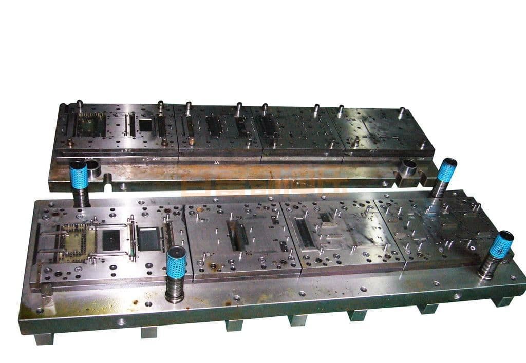
I. Design Principles for Progressive Die Strip Layout Drawings
Before blanking flat stamping parts (including flat blanks for various formed stamping parts—hereinafter the same), economical and rational arrangement and layout on sheets, strips, ribbons, and coils are performed to conserve material, achieve the optimal nesting, and attain the highest possible material utilization rate. In cold stamping process design and die design, this is an important and technically demanding task; in cold stamping die structure design, the stamping part drawing, stamping process, and its strip layout drawing serve as the primary basis.
In known professional publications, the strip layout for single-station blanking dies and compound dies is described in detail, but the strip layout for multi-station progressive die stamping is not covered.
The strip layout drawing for multi-station progressive stamping parts should fully illustrate the stamping process and the sequence of stamping steps, and indicate the feed pitch, specific data for the web and bridge (scrap allowance), the feeding method between stations, as well as all stamping processes, deformation, and separation operations of the stamping part.
Die selection, structural design, stamping material utilization rate η, and stamping productivity are closely related to the production cost of stamping parts, but they also affect the quality of the stamping parts and die life. The strip layout should fully consider the material supply and the production conditions of the stamping equipment. On the basis of ensuring stamping quality, efforts should be made to achieve a better die structure, better operational safety, and better die manufacturability. All factors affecting the strip layout should be comprehensively analyzed, and multiple alternatives should be compared to select the optimal layout.
Before commencing die stamping design, the die stamping drawing and strip layout drawing should be analyzed to understand the key technical requirements and stamping difficulties. Based on the rationality of the stamping process and potential issues that may arise, a foundation should be laid for the die stamping structure design.
Among the many single-operation stamping dies, only blanking dies and single-station compound dies require the design of a strip layout. That is, when blanking flat stampings and developed flat blanks of formed stampings, strip layout is necessary. Moreover, most of these are conventional strip layouts with scrap around the part and along the edges, and most can only achieve scrap-reduced blanking. Regardless of the strip layout method used, the rationality and advantages/disadvantages of the layout are generally measured by material utilization.
The strip layout for progressive die stampings differs from the above. Material utilization η is not the most important or the only criterion for evaluating the quality of the strip layout.
For the strip layout of progressive die stampings, it is necessary to analyze the stamping process, rationally design the stamping process flow and its sequence, fully consider the characteristics of progressive stamping and the needs of die structure design, and pay attention to the selection of feeding methods between stations and the design of the positioning system.
Therefore, the strip layout for progressive die stampings is based on the design of progressive stamping process steps, with ensuring the quality of the stampings and their dimensional and geometric tolerances as the core, with the arrangement of stamping process steps and the selection of inter-station feeding methods as the guide, and with the selection of die types and structural design as the purpose. The basic principles to be followed are as follows:
(1) It is conducive to selecting simpler die types and structures, ensuring operational safety and good stamping quality.
(2) The die has good manufacturability, is easy to grind and maintain, has a short manufacturing cycle, and low manufacturing and maintenance costs.
(3) The sheet material utilization η is high.
(4) The die life is longer.
(5) The stamping efficiency is higher, and the production cost of stampings is lower.
Among the above five principles, item (1) is the most important.
Sometimes it is impossible to satisfy all requirements simultaneously; in such cases, the user's requirements and delivery schedule should be given priority, and other terms may be relaxed appropriately. In many cases, a higher material utilization rate η often complicates the die structure, making die manufacturing more difficult, and may even exceed the capabilities of existing die-making equipment and technology. In such situations, even the best layout and highest η value must be abandoned. Some prefer to sacrifice material utilization η to achieve better die manufacturability, shorter die manufacturing cycles, and longer die life.
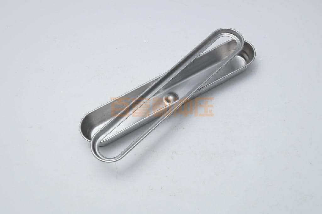
II. Selection of Layout Forms and Their Relationship with Die Types and Structures
For blanking dies and compound dies with a single station, the layout patterns for flat blanking parts and developed flat blanks of various formed stampings on sheets, strips, bands, and coils typically include: single-row straight layout, single-row angled layout; double-row parallel straight layout, double-row head-to-head straight layout, double-row head-to-head angled layout; multi-row straight layout, staggered layout, and mixed layout, among others.
Different layout patterns yield different material utilization rates. The selection of a layout pattern should first consider achieving the required dimensional and geometric tolerances of the stamping, and then determine the appropriate die type and structure.
For example, if the dimensional accuracy requirement is IT10 or higher, a layout with scrap web and bridge (carrier) should be used. Parts produced with scrap-free layouts generally have poorer dimensional accuracy, typically below IT12, or even as low as IT14. If the dimensional accuracy is as high as IT9 or above and flatness is required, a die with a sliding guide pillar die set and a spring-loaded stripper plate should be selected, and the layout should provide sufficient scrap web and bridge widths.
According to German Industrial Standard DIN 1543, cold-rolled steel sheets are classified by thickness t: t < 3 mm is considered thin sheet.
In the production of instruments, meters, and electronic products, ultra-thin foil stampings with t ≤ 0.3–0.1 mm, or even ≤ 0.1–0.05 mm, are frequently used, which poses many challenges to stamping layout and die design.
The scrap web and bridge widths, as well as the blanking clearance, all vary with the material thickness t of the stamping.
When t ≤ 0.5 mm, the bridge and scrap web widths should be greater than t to prevent the material from being pulled into the die opening during blanking, and to ensure sufficient strength and good feeding stiffness of the carrier strip. For low-carbon steel sheet with t = 0.3 mm, according to the Class I clearance specified in GB/T 16743-1997 "Blanking Clearance," the single-side clearance can be taken as 3% t, i.e., c = 3% × 0.3 mm = 0.009 mm. For t = 0.1 mm, c = 0.003 mm, i.e., 3 μm. However, the guide pillar and guide bushing fit clearance specified in GB/T 2854-90 for Class I sliding guide pillar die sets is 0.010–0.016 mm. Therefore, when blanking and progressive stamping such ultra-thin materials, special attention must be paid to selecting an appropriate layout pattern and designing a reasonable and precise die structure; otherwise, it will be difficult to complete the stamping of such parts and achieve the required dimensional and geometric tolerances.
For progressive stamping of ultra-thin parts with t < 0.5 mm, the bridge and scrap web widths in the layout can be equal, and may be appropriately increased depending on the die structure design requirements. In terms of die structure type selection, a guide pillar die set with a spring-loaded stripper guide plate is recommended, and it is best to mount the spring-loaded guide plate on the guide pillars and install small guide pillars on the stripper plate (guide plate) to ensure precise guidance and improve stamping accuracy. The coaxiality and positional accuracy of the group of holes in the part impose higher requirements on the layout feed pitch accuracy and the die feeding and positioning. Special attention should be given to this during layout design.
For ultra-thin stampings with material thickness t≤0.1mm, especially complex-shaped parts produced in multi-station progressive dies, it is not advisable to use multi-row diagonal nesting, head-to-head nesting, or flip stamping, and mixed nesting is even less recommended. Otherwise, the carrier strip is prone to deformation, tearing, or even being pulled into the die during feeding, which affects production, increases scrap and defective parts, and damages the die. For medium-thick plate stampings with t≥3mm, scrap-free nesting with carriers is not recommended; for stampings with t≥4.75mm, nested or interlocked blanking layouts are not recommended, as they will complicate die structural design.
For high-precision foil stampings with dimensional accuracy ≤±0.01mm and material thickness t≤0.1mm, especially those with complex shapes and precision higher than IT9 grade, a ball-bearing guide-pin die set with spring-loaded stripper and guide-plate die structure is recommended.
Key points in strip layout design: For single-station blanking dies and compound dies, the strip layout is designed by arranging the flat blank outline of the stamping or the developed flat blank of the formed part repeatedly on the strip or coil. The goal is to select the optimal nesting method that ensures product quality and process efficiency while simplifying die structure and manufacturing, achieving the highest possible material utilization. Generally, the shape and dimensions of the blank determine the nesting type, and traditional nesting with scrap allowance (web and bridge) is mostly adopted for blanking with scrap.
Based on years of practical experience, for the strip layout design of single-operation blanking, compound blanking, and single-station combined compound stamping, the part can be considered as a flat blank or developed blank for one-time blanking. Progressive die strip layout is much more complex than single-operation dies. The layout must ensure smooth continuous stamping, achieve the highest possible material utilization (η), ensure operational safety and high efficiency, and involves many influencing factors and high requirements. The steps and key points are as follows:
(1) After thorough process analysis of the stamping, study the feasibility of producing the part in one progressive die, propose multiple stamping process schemes for comparison, select the best one, and then proceed with the strip layout.
(2) The shape, dimensions, and accuracy of the stamping directly affect the progressive stamping process and the sequence of operations. When designing the layout, consider the manufacturability of progressive stamping and the structural design requirements of the die. Pay attention to the following points in the sequence of operations and station arrangement:
a. Holes in a group that require hole-to-hole center distance accuracy of IT10 or better, or with tolerance less than 0.01mm, should be punched in the same station or in two adjacent stations;
b. If the distance from a hole wall or hole edge to the part edge is less than the material thickness t or less than 2mm, the hole should be punched in two separate steps (stations) to enhance die strength and provide more mounting space for the punch in the punch retainer;
c. For holes with very high coaxiality or positional accuracy requirements (tolerance less than 0.01mm), the related holes can be punched in one operation or in two adjacent stations. Areas requiring clean punching or blanking should be concentrated in one or two stations;
d. If the dimensional tolerances of the part outline or the developed blank of the formed part are very tight, consider blanking the entire outline first and then bending or drawing. If local bosses or notches have tight dimensional requirements, use multiple stations to punch them separately and then combine them.
e. For high-volume production of small, complex-shaped stampings, multi-station progressive dies should be used as much as possible to form the part in one die, thereby improving part quality and efficiency;
f. For high-precision stampings requiring dimensional accuracy of IT10 or better, the number of stations in the strip layout should be minimized to prevent excessive accumulated feed error from too many stations, which would reduce stamping accuracy. Dedicated stations should be arranged for local fine blanking, upsetting/extruding, and flattening operations;
h. For stampings with complex multi-directional bending, side piercing, forming, or notching that require lateral force application, consider using wedge-driven lateral stamping in one die after flat piercing/notching or before blanking, to improve accuracy and efficiency.
(3) Considering the needs of die structure design and the space required for stamping deformation, set necessary idle stations and enlarge the mounting area for punches in the punch plate; if material is flattened or thinned to increase the die surface area for covering, also add idle stations to increase die wall thickness.
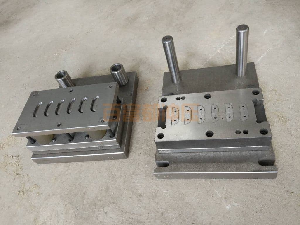
III. Strip Layout Types and Methods for Progressive Die Stampings
Based on the process characteristics of progressive die stamping, including station-to-station feed method, presence or absence of scrap web in the layout, and methods for trimming process scrap, the strip layouts for progressive die stampings can be categorized into the following types and arrangement methods:
1. Split-and-Combine Layout
Each station independently pierces and forms a portion of the stamping; the stations are relatively independent and unrelated, with their relative positions controlled by the die, and finally combine to form a complete, qualified part (see Figure 1a, b, f, j).
2. Segment-and-Join Layout
The internal holes and external contour, or even a complete arbitrarily shaped blanking line, are pierced or cut in several separate stations and then joined to form the complete part. Although similar to the split-and-combine layout, it is not identical. In this layout, the cutting edges of each station are interrelated, and the interface portions must overlap, increasing die manufacturing difficulty.
3. Stamping with scrap strip trimming layout
The method of obtaining the complex outer contour of the side of a stamping by trimming along the edge of the strip is called trimming along the edge layout. When the length l of the trimmed edge in the feeding direction is equal to the feed pitch s, i.e., l = s, the punch can replace the side trimmer and also perform the task of trimming and positioning the incoming raw material. Such side punches are commonly referred to as forming side trimmers. Due to the limited variety and size range of standard side trimmers per JB/T 7648.1-94, the maximum trimming length is only 40.2 mm. When the feed pitch s > 40.2 mm, only non-standard side trimmers can be used.
Another disadvantage of using standard side trimmers is that a certain width of material must be removed from the side of the raw material to form a notch equal to the feed pitch for positioning the incoming material, which increases process scrap and reduces the material utilization rate η by 2% to 3%. Using a side punch to trim along the edge not only completes the blanking of any complex outer contour on the side of the stamping but also limits the feed pitch of the incoming material, replacing the standard side trimmer—a multi-purpose solution.
4. Trimming scrap layout
For long, thin stampings, especially those with complex outer contours to be blanked at the areas connected to the scrap web, the trimming scrap layout can achieve high quality and productivity, avoiding issues such as distortion of slender stampings and difficulty in stripping. Typical examples include instrument pointers and watch second hands, where this layout works very effectively. To facilitate die manufacturing, the scrap web is sometimes enlarged for easier blanking, and the stampings left on the raw material as part of the web are finally separated by cutting.
5. Combined trimming and scrap web blanking layout
The layout in which the developed blank of the formed stamping is obtained by progressively trimming along the edge and the scrap web at different stations, followed by forming, is called the combined trimming and scrap web blanking layout. At each station, process scrap is removed, and the stamping remains on the raw material, gradually taking shape until it is separated at the final station. This layout keeps all stations on the same plane, arranged linearly along the feeding direction, with the raw material carrying the workpiece between stations. The die structure is simple, and operation is convenient and safe.
6. Nested layout
Using the structural scrap from the internal hole of a larger stamping to produce smaller stampings of the same material at a dedicated station in the same progressive die is called a nested layout.
Generally, the smaller stampings from the internal hole are blanked first, and the larger stamping is typically blanked at the final station.
Using a single-station compound blanking die to nest washers is a classic example of nested layout that has long been well known. For multi-station progressive blanking parts, nested layout—where there is no scrap bridge between upper and lower stations—requires high coaxiality, and the feed pitch must be small to ensure the dimensional and positional accuracy of the nested blanked parts.
7. Scrap-blank layout
Scrap-blank layout involves using process scrap and structural scrap connected along the edges to blank multiple parts of the same material by combining them together. The difference from nested layout is that scrap-blank layout maximizes the use of process scrap, excess edge scrap, and structural scrap generated by complex part contours with significant convex and concave differences, to blank multiple parts of the same material. During layout, the convex and concave features of the part contours are fully utilized, interlocking and nesting the parts together to make the most efficient use of the raw material.
Scrap-free blanking and no-scrap-blank layout: Since the vast majority of progressive die parts use layouts with edges and scrap bridges, only scrap-producing blanking is possible. If a layout without edges and without scrap bridges can be achieved, and the blanked parts also produce no structural scrap, then scrap-free blanking can be performed. Truly complete scrap-free blanking, where material utilization reaches or approaches 100%, is rare. However, any part that can be laid out without scrap bridges can be blanked with minimal scrap.
To implement scrap-free or minimal-scrap blanking for blanked parts, the first step is to perform a no-scrap-bridge layout for the blanked parts.
Implementing a no-scrap-bridge layout requires certain conditions and methods. In addition to the progressive die parts mentioned above that can use no-scrap-bridge layouts for scrap-free or minimal-scrap blanking, single-operation dies and single-station compound blanking dies can also do the same.
4. Layout method for progressive compound dies with non-linear feeding
In most progressive dies, the feeding direction is linear on the same plane, and each station is fed using the method of carrying the raw material forward. For this reason, the parts are connected by scrap bridges and remain on the raw material for stamping at each station. Only after processing is complete at the final station can the finished parts, connected by scrap bridges, be separated from the raw material. For some complex-shaped parts with large bending heights, deep drawing depths, and the need for multi-directional bending forces, it is often necessary to blank the entire part first and then form it in a separate die.
Otherwise, the die would need a large opening height to remove the formed part from the die cavity. If a conventional progressive die were used with all stations arranged linearly on the same plane along the feeding direction, the die structure design would become difficult.
For such parts formed in a single multi-station progressive die, the layout method is completely different from the conventional progressive die layouts described above. After blanking the developed flat blank, a wedge-driven special feeding mechanism pushes the blank to a forming station positioned at an angle to the raw material feeding direction, where bending or drawing is performed. This results in the die stations being arranged in an L-shape, and the stations are not on the same plane.
With the rapid development of modern stamping technology, the continuous improvement of stamping mechanization and automation, and the higher requirements for stamping safety production, progressive dies of this structure will be increasingly widely used.
The three-station continuous compound die for the lifting ring stamping part has the first station for piercing rectangular holes, the second station for blanking and bending compound stamping, and the third station is a feeding system driven by the cam driver (part 8). After the bent workpiece from the second station is pushed into position along the bending core (part 12) by the push plate (part 6), two sets of cam drive mechanisms (part 13) apply force relatively and perpendicular to the feeding direction, pushing a pair of forming dies (part 17) to finally form the stamping workpiece. This die has both the action characteristics of a progressive die and the functions of a compound die. Since the transition from the second to the third station involves the workpiece being separated from the raw material and formed separately, calling it a progressive die does not match reality;
calling it a continuous die ignores the compound stamping function of the second station and the overall characteristics of separation and deformation compound stamping of the entire die. Therefore, naming it a continuous compound die is more appropriate.