
I. Key Factors in Determining the Technical Performance of Automotive Tension Parts
1. Determining the drawing direction: Judging the drawing direction of a part is the first issue encountered when defining the drawing process. It not only determines whether a satisfactory drawn part can be produced, but also affects the amount of process compensation and the shape of the blank holder surface. Correctly determining the stamping direction should meet the following three requirements.
(1) Ensure that the punch can enter the die. The shape at the lower right corner of the die protrudes outward, and the protruding point exceeds the die dimensions, preventing the punch from entering the die, making drawing in that direction impossible. Therefore, it is necessary to change the drawing direction so that the punch can enter the die.
(2) Ensure a large contact area between the punch and the blank. The larger the contact area, the smaller the angle between the contact surface and the horizontal plane. This reduces the likelihood of stress overloads that could cause part fracture. Improving the die-fitting function during drawing and easily achieving a good punch shape are beneficial for increasing the degree of part deformation.
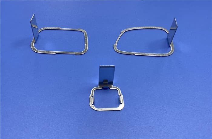
(3) Ensure uniform feed resistance across the blank holder surface. Uniform drawing is a condition for ensuring even feed resistance across all parts of the blank holder surface. Uniform feed resistance is an important guarantee for preventing wrinkling and cracking in the drawn part.
2. To complete the drawing process, it is often necessary to add process compensation material to the part, thereby achieving a satisfactory drawing result.
The advantages and disadvantages of technical compensation are important indicators of the quality of the drawn part design. Reasonably adding compensation material should meet the following three requirements:
(1) Process drawing requirements.
(2) Blank holder requirements.
(3) Trimming and flanging operations required after drawing.
II. What effects does multiple drawing have on drawn parts?
1. Multiple drawing significantly improves the pass rate during production and reduces the likelihood of scrap, because after multiple draws, stress relief and annealing softening are performed in between.
2. Multiple drawing ensures product precision and greatly increases the elongation coefficient and production efficiency.
3. Since one-shot forming requires high technical expertise, multiple drawing can enhance uniformity and reduce the product rejection rate.
III. Considerations when selecting automotive drawn parts
(1) For the production of drawn parts, standard mold bases should be selected whenever possible. The type and specification of the standard mold base determine the type and specification of the upper and lower die holders.
(2) The selected or planned mold base must be compatible with the relevant dimensions of the press table and associated slide, and necessary checks should be performed. For example, the minimum trimming dimension of the lower die holder should be at least 40–50 mm larger than the blanking hole size of the press table.
(3) For large precision molds, choose mold bases made of ZG35 or ZG45.
(4) The parallelism between the upper and lower surfaces of the mold base should meet requirements, with the parallelism tolerance generally at grade 4.
(5) The mounting holes for guide bushings and guide pillars in the upper and lower mold bases must be interchangeable, with precision generally required to be within ±0.02 mm. The axes of the guide pillar and guide bushing mounting holes should be perpendicular to the upper and lower surfaces of the mold base. The axial alignment for installing guide pillars and guide bushings should be perpendicular to the upper and lower surfaces of the mold base, and the installation of guide pillars generally requires grade 4 accuracy.
(6) The surface roughness of the upper and lower surfaces of the die set should be Ra1.6~0.8μm. If parallelism can be guaranteed, it can be reduced to Ra3.2~1.6μm. The function of the backing plate is to directly receive and disperse the pressure transmitted by the punch, reduce the unit pressure on the punch, and prevent the die base from being pressed in. The shape and dimensions of the backing plate are the same as those of the die, and it is fixed using screws and dowel pins.
The above is related content on the processing of automotive drawn parts. The processing of drawn parts must meet the product's service performance and technical performance, and must also undergo assembly and fitting. This allows for full utilization of metal materials, reduces the types and standards of data, minimizes material consumption, selects lower-cost information when qualified, and strives to make parts as waste-free and low-waste as possible. I hope the above content is helpful to the readers.