Material-specific planning for stainless steel, aluminum, copper alloys, nickel alloys, titanium, tantalum and controlled-expansion metals.
Material selection is part of the process design
Deep-drawn parts can be produced from far more than low-carbon steel. Balford evaluates the material together with the part geometry, drawing depth, wall requirement, surface specification and operating environment.
Each alloy behaves differently under tensile and compressive strain. Draw ratios, radii, lubrication, blank holding, tool materials and intermediate heat treatment must be adapted accordingly.
Materials we evaluate for deep drawing
Cold-rolled steel
Stainless steel
Aluminum
Copper and brass
Monel® nickel-copper alloys
Titanium
Hastelloy® nickel alloys
Kovar® controlled-expansion alloy
Invar controlled-expansion alloy
Mu-metal / permalloy
Inconel® nickel alloys
Tantalum and other specialty alloys
What changes from one alloy to another?
Nickel alloys and titanium may demand high forming loads and carefully selected lubrication. Copper alloys provide useful conductivity but require surface protection. Controlled-expansion and magnetic alloys are selected for very specific functional behavior and must be formed without compromising those properties.
A material certificate alone is not enough. Actual strip condition, temper, thickness variation and grain direction should be considered during trials.
Developing a reliable special-alloy part
Send the drawing, target alloy, expected volume and functional requirements at the start of the review. Balford can assess manufacturability, propose a forming sequence and identify where prototype trials or material samples are needed before production tooling is finalized.
Discuss Your Component
Need a stable production process for a difficult metal part?
Send Balford your drawing, material, annual quantity and quality requirements. Our engineering team will review the forming sequence and recommend a practical manufacturing route.
Beyond common steels and aluminum, Balford evaluates deep drawing in titanium and titanium alloys, nickel and Monel, Kovar, Invar and other controlled-expansion alloys. These materials are chosen for demanding applications: high temperature, corrosion, magnetic control or matched thermal expansion. They also form differently — higher springback, stricter lubrication needs and narrower process windows.
Design Considerations
Material certification and lot consistency matter more for special alloys. The drawing should state grade, temper, thickness and any traceability requirement. Because tooling and process development cost more for exotic alloys, the drawing review should confirm that the special material is functionally necessary before the route is committed.
Frequently Asked Questions
Can titanium be deep drawn? Yes, commercially pure titanium and some alloys can be drawn with careful tooling and lubrication; forming is typically slower with tighter process control. Feasibility is confirmed from the actual drawing.
What about Kovar and Invar? These controlled-expansion alloys are drawn for glass-to-metal seals and precision instrumentation. The forming window is narrower, and annealing between stages is often required.
Published:
Tooling, work-hardening and surface-control considerations for demanding stainless-steel drawn parts.
Why stainless steel is selected
Stainless steel combines corrosion resistance, strength and durability across wet, chemical, high-temperature, low-temperature and high-pressure environments. These properties make it attractive for structural, wear-resistant and precision housing applications.
The same properties make stainless steel more demanding to deep draw than many conventional sheet materials.
Work hardening and forming difficulty
Stainless steel can harden rapidly under cold work. Local over-strain affects later piercing, machining and dimensional control, while high forming forces increase demands on die strength, alignment and wear resistance.
Draw ratios, radii, blank-holder force, lubrication and station sequence must be selected to control cracking and wrinkling while maintaining a uniform wall.
Precision features beyond the draw
A successful stainless process may include fitting surfaces, pierced features and controlled edges in addition to the basic drawn form. Venting inside the tool is important where trapped air could affect the component. Edge finishing and final sizing must be planned from the beginning.
Balford has developed stainless drawing sequences that can avoid intermediate annealing for suitable materials and geometries, reducing handling while maintaining precision.
In-house die development
Tool design and manufacture are coordinated with the required material and geometry. Engineers calculate the number and order of forming stages and evaluate whether conversion from a welded or machined process can lower cost.
The development team verifies every stage through tool trials and measurement before approving the process for production.
Applications and process conversion
Drawn stainless components are used in containers, housings, fittings and industrial assemblies where corrosion resistance and long service life matter. When considering a new design, early review of material grade, wall requirement, annual volume and functional surfaces helps identify the most economical route.
Discuss Your Component
Need a stable production process for a difficult metal part?
Send Balford your drawing, material, annual quantity and quality requirements. Our engineering team will review the forming sequence and recommend a practical manufacturing route.
Stainless steel grades used for deep drawing include 304/304L, 316/316L, 430 and ferritic grades. Austenitic stainless work-hardens quickly, which is useful for strength but raises forming loads and springback; ferritic grades offer lower hardening but can be prone to ridging on the surface. Grade, temper and surface condition must be specified at RFQ because they change the draw plan completely.
Design Considerations
Use generous radii, plan for intermediate annealing on deeper draws, and control lubrication to avoid galling. Wall thinning is a design input, not an afterthought: critical wall sections should be defined with a measurement method. For precision components, dimensional stability after drawing depends on the tooling sequence and the inspection datum scheme.
Applications
Stainless deep drawn parts include sensor housings, solenoid bodies, medical enclosures, kitchen and sanitary hardware, and food-grade fittings — applications where corrosion resistance, cleanliness and wall integrity are functional requirements.
Frequently Asked Questions
Can 304 stainless be drawn to tight tolerances? Yes, with a validated draw sequence and datum-based inspection. Springback and work hardening must be accounted for in tooling compensation.
Is passivation needed after deep drawing? Drawing and trimming can disturb the passive layer; passivation restores corrosion resistance and is recommended for critical applications. Specify the standard (e.g. ASTM A967) at RFQ.
Published:
Locally increasing wall thickness can strengthen a one-piece stamping and remove washers, welds and excess material.
What is local thickening?
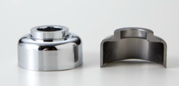
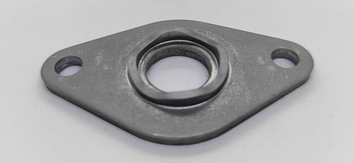
Local thickening is an integrated forming method that moves material into a selected area so one component can contain both thin and thick sections. The reinforced area can improve strength and durability without increasing the gauge of the entire blank.
The technique also gives designers more freedom to create functional transitions and curved forms that would be difficult to obtain through conventional stamping alone.
A high-strength material example
Balford developed a multi-stage process that locally increased a high-strength material to approximately twice its original sheet thickness while controlling buckling, folding and cracking. In the formed region, work hardening increased strength to about 1.5 times that of the starting material.
The original assembly used a stamped cup, a separate washer and welding. Forming the thickened feature directly into the cup converted the design into a single stamped component.
Three ways the process can reduce cost
Less material: only the area that needs additional strength is thickened, so the whole part does not require heavier sheet.
Fewer operations: washers, welding, riveting or secondary rolling may be eliminated.
Lower weight: targeted reinforcement balances strength and mass, reducing material and transport impact.
Forming control
High-strength sheet has lower ductility and creates greater forming load than conventional steel. Dividing material movement across several calculated stages is essential to prevent fracture and unwanted folds.
Tooling simulation, die development and controlled tryout are used to establish a repeatable production window before volume manufacture.
A practical route to part consolidation
Local thickening is most valuable when the current design carries extra gauge everywhere or joins several elements only to reinforce one location. Balford can review the assembly and assess whether a one-piece precision stamping can meet the same functional requirement.
Discuss Your Component
Need a stable production process for a difficult metal part?
Send Balford your drawing, material, annual quantity and quality requirements. Our engineering team will review the forming sequence and recommend a practical manufacturing route.
Local thickening (also called upsetting or coining-based thickening) concentrates material in a defined zone — a boss, rib, gear tooth or threaded area — by displacing metal under controlled pressure. It allows a thin blank to carry locally thicker material where function demands strength, without machining from thicker stock.
Design Considerations
Material volume is conserved: the thickened zone must be fed by surrounding material, so the blank and tool geometry are calculated together. Flow direction, grain structure and achievable thickening ratio depend on material ductility and press force. Functional requirements (height, hardness, flatness) should be defined with tolerances so the coining station can be designed to hold them.
Frequently Asked Questions
How much can a part be locally thickened? The practical ratio depends on material and geometry — typically up to 30-50% of the base thickness in one step, with staged coining for more. Feasibility is confirmed by engineering simulation and sampling.
Does thickening affect tolerances elsewhere? Material flow can shift adjacent features, so critical dimensions near the thickened zone need a datum strategy. Balford reviews the drawing holistically before tooling.
Published:
Fine Blanking technology plays a crucial role in the manufacturing of metal parts for industries such as automotive, medical, electronics, industrial, and furniture. This advanced metal forming process has brought revolutionary changes to the manufacturing industry, making the production of high-precision, high-quality parts more efficient and economical.
What is fine blanking process
Fine Blanking, as the name suggests, is a precision metal cutting process. It has evolved from traditional stamping techniques but offers significant improvements in both manufacturing principles and processing results.
This advanced technology has enabled manufacturers to produce complex parts with tight tolerances and superior surface finish in a single operation, which would otherwise require multiple secondary operations using conventional stamping methods. The ability to produce near-net-shape components with minimal material waste and reduced post-processing requirements has made Fine Blanking an attractive option for various industries seeking cost-effective solutions for high-volume production of precision parts.
fine blanking vs conventional blanking
Fine blanking technology represents a significant improvement over traditional stamping processes. While traditional stamping is fast and cost-effective, it often falls short of meeting the stringent precision and surface quality requirements of high-end manufacturing industries. In contrast, fine blanking technology, through innovative process design, achieves remarkable advantages.
The fine blanking process virtually eliminates deformation at the edges of parts, ensuring geometric precision. Our fine blanking technology can control flatness and perpendicularity to within 0.03mm, and can even achieve extremely high precision of up to 0.01mm. The smooth sheared surface of fine blanked parts can reach over 90% of the material thickness, greatly enhancing the product’s aesthetics and functionality.
Furthermore, the fine blanking process produces minimal fracture zones, and burrs are almost negligible. After barrel polishing treatment, a completely burr-free smooth surface can be achieved. Fine blanking technology also ensures high precision of the cut surface, greatly improving the assembly performance of parts.
fine blanking vs conventional stamping
Under the same quality requirements, fine blanking technology, with its high-efficiency characteristics, has become an ideal alternative to traditional processes such as machining and powder metallurgy. Fine blanking not only significantly improves production efficiency but also substantially reduces processing costs, creating higher value for customers. This perfect combination of high efficiency and low cost has led to the increasingly widespread application of fine blanking technology across various industries.
Custom Metal Fine Blanking
Our fine blanking technology is utilized in diverse industries, producing high-precision metal parts for automotive gears, medical instruments, electronics connectors, and industrial valves. We maintain industry-leading precision and efficiency with advanced equipment and stringent quality control measures. Continuous innovation drives us to meet evolving customer needs. Our flexible production lines cater to personalized requirements, ensuring swift and reliable delivery services for urgent orders.
Process sequencing, reverse drawing and material control for complex precision-formed components.
Why complex drawing is difficult
Deep drawing is already one of the more demanding stamping processes. When the part combines non-cylindrical walls, openings, flanges and multiple forming directions, the finished geometry cannot be achieved by simply adding stations in an obvious order.
Tooling engineers work backward from the completed part to define how material must flow at every stage. The sequence, radii, draw depth and restraint must control stretch and compression without losing dimensional accuracy or uniformity.
Combining forward and reverse drawing
Balford combines multi-stage deep drawing with reverse-draw methods for difficult shapes. A part may first be formed deeply in the normal press direction, then redrawn in the opposite direction before a flange or final feature is formed.
This coordinated material movement enables geometries that would be difficult to produce with a single-direction process.
Aluminum forming considerations
Complex aluminum parts can provide major weight savings; aluminum is approximately one-third the density of steel. This is useful in electric vehicles and other applications where every gram matters.
Aluminum also transfers heat quickly, is relatively soft and can adhere to tooling. Speed, cooling, lubrication, die material and surface condition all require careful control to avoid cracks, wrinkles and galling.
Process controls for stable quality
Accurate design and manufacture of multi-stage tooling
Material selection and forming-condition validation
Control of stress, strain, cracking and wrinkling
Consistent dimensional accuracy and surface finish
Balford reviews how many operations are necessary, in what order the geometry should be formed and whether a process conversion can reduce total cost. This development work continues through tool tryout and sample validation.
From requirement to production method
The engineering team evaluates cost, quality and function together. Rather than forcing a drawing into a standard route, the aim is to propose a process that fits the product requirement and is stable enough for production.
Discuss Your Component
Need a stable production process for a difficult metal part?
Send Balford your drawing, material, annual quantity and quality requirements. Our engineering team will review the forming sequence and recommend a practical manufacturing route.
Complex deep drawing combines multiple draws, flanges, steps, embossed details and trimmed openings in one formed component. The process plan must sequence the draws so material keeps flowing from the flange toward the walls, avoiding excessive thinning at radii and uncontrolled wrinkles on the flange.
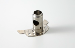
At Balford we review blank shape, draw sequence, lubrication, blank-holder pressure and intermediate annealing (where required) as one system. Features such as side openings, sharp steps or tight bottom radii are evaluated for staged operations — piercing after drawing, ironing, coining or local extrusion — rather than forced into a single draw.
Applications
Complex deep drawn parts include solenoid housings, sensor bodies, motor cans, fuel-system components and pressure-vessel end caps. These parts combine sealing surfaces, controlled wall sections and tight positional tolerances between features formed in different stages.
Frequently Asked Questions
How many draw stages does a complex part need? That depends on depth-to-diameter ratio, material and feature severity. The drawing defines the number of stages; Balford proposes and validates the sequence during engineering review.
Can secondary features be added after drawing? Yes — trimming, piercing, threading, annealing, surface treatment and assembly can be coordinated. Defining them at RFQ lets the team protect wall condition and datums through the full route.
Updated:
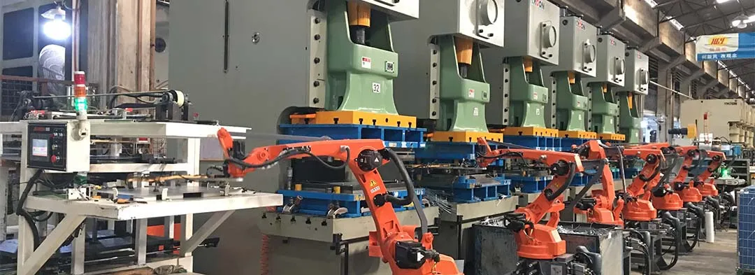
Balford has always aimed to optimize manufacturing processes with the goal of improving efficiency and reducing costs, which serves as the core competitive advantage of our factory. To achieve this, we have introduced the “In-Die Tapping” technology, which plays a crucial role in the field of progressive die stamping.
In traditional manufacturing processes, the stamping and threading operations for parts with threaded holes are typically carried out separately, leading to increased production complexity and reduced efficiency. By integrating In-Die Tapping units into the progressive die stamping process, threading is directly incorporated into the die.
This technique cleverly merges traditional threading processes with stamping operations, achieving efficient, high-precision, and automated production. By streamlining the production process and reducing the need for secondary operations, we have significantly enhanced production efficiency and product quality.
We are continuously dedicated to innovation, providing customers with competitive and sustainable solutions. We actively adopt various processing technologies that enhance efficiency, continually optimizing our manufacturing processes. Through team enhancements and technology integration, we have fulfilled our commitment to sustainable practices.
in-die tapping FAQ
The in-die tapping unit is a specialized equipment used to assist in generating threads during stamping forming. It combines traditional stamping and tapping techniques by converting the up-and-down movement of the press slide into the spiral motion of an extrusion tap for thread formation.
In-die tapping technology is suitable for continuous die sets, progressive die sets, and precision die sets, achieving chipless processing, avoiding secondary operations, improving production efficiency and cleanliness, and enhancing thread strength. The working principle of the in-die tapping machine involves the reciprocating motion of the press slide to complete various functions such as feeding, positioning, material punching, and bending to achieve thread forming. This technology is applicable to various thread hole processing, including blind holes, with wide adaptability, and can significantly enhance production efficiency and product quality in metal parts manufacturing. It is frequently employed in the sheet metal stamping industry for threading materials like aluminum, brass, and stainless steel.
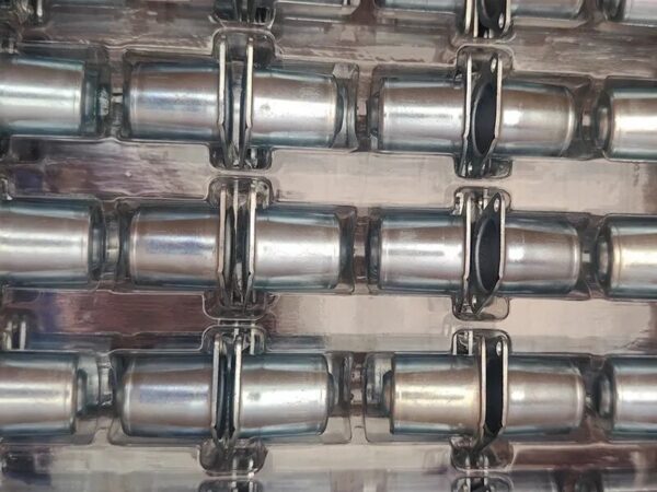
Precision rotary trimming removes excess material from drawn sleeves and housings inside the progressive die.
What is precision in-die rotary cutting?
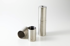
In-die rotary cutting uses a controlled rotary mechanism to remove excess material from the open end of a drawn cylindrical part. It is commonly applied to sleeves, bushings and housings where a clean, accurately located end face is required.
For suitable parts, Balford can trim a flange-free deep-drawn component directly inside the die. This avoids a separate lathe or secondary trimming station and supports a more energy- and material-efficient production route.
Rotary die structure
A rotary cutting station typically combines a cutting element, drive mechanism, guide components and part-location features. Tool geometry, working angle and cutting path are calculated from the component shape and edge requirement.
Stable guidance prevents lateral movement while the location system controls the part position. The die structure must also manage material flow, cutting load, wear and safe part release.
Controlling edge quality
Edge quality depends on material hardness and ductility, trim allowance, cutting clearance, feed, cutting load and tool condition. Coordinating these variables reduces burrs and distortion and can hold end-face accuracy below 0.10 mm where the component and process permit.
Materials, press and die life
Working components require wear resistance, impact resistance and thermal stability. Alloy tool steels and carbide elements may be selected according to production volume and material. The press and feed system must provide the accuracy and stability needed to keep every station synchronized.
Strip layout and pitch
The strip layout determines material utilization, station loading and production stability. Pitch must accommodate the press stroke, part geometry and rotary mechanism while maintaining enough carrier strength to move the part through each forming stage.
Debugging and production control
During tryout, the team checks installation, clearances, edge condition, part location and tool wear. Results from sample inspection guide adjustments to the die structure and operating parameters before volume production.
The outcome is an integrated cutting operation that can improve throughput, reduce secondary machining and deliver consistent ends on circular deep-drawn parts.
Discuss Your Component
Need a stable production process for a difficult metal part?
Send Balford your drawing, material, annual quantity and quality requirements. Our engineering team will review the forming sequence and recommend a practical manufacturing route.
Rotary cutting in a progressive die replaces a conventional blanking station with a rotating punch and die that cut on a rolling contact. The result is lower peak force, reduced shock to the press and tooling, and cleaner cut edges on suitable materials — which is why rotary cutting is used for thin-strip contacts, battery terminals and connector parts where burr control matters.
Design Considerations
The cut profile must suit the rotary motion: straight edges parallel to the feed direction behave best, while complex contours need careful angular mapping. Material thickness, hardness and surface condition affect tool life and edge quality, so the material specification should be fixed before tooling is committed.
Frequently Asked Questions
Does rotary cutting cost more than conventional blanking? Tooling is more complex, but tool life and part quality often offset the difference on high-volume programs. The comparison should be made on cost-per-part, not tooling alone.
Which materials work best? Copper alloys, brass, aluminum and low-carbon steels are common. Hard or abrasive materials can be processed, but tooling strategy and maintenance intervals need to account for wear.
Published:
A practical guide to multi-directional forming, side punching, material savings and integrated assembly.
What is a multi-slide stamping machine?
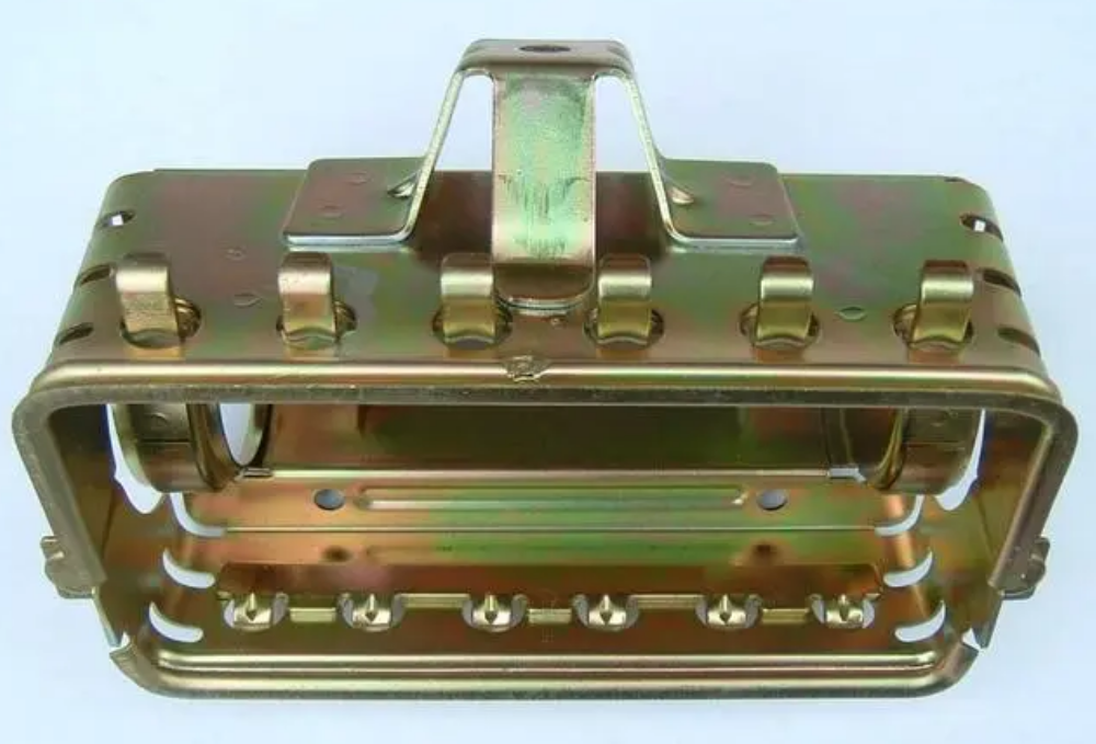
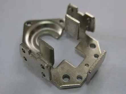
A multi-slide or four-slide machine can be understood as a horizontally acting stamping system in which cam-controlled slides approach the workpiece from several directions. Unlike a conventional press that primarily moves up and down, the forming tools can work at right angles around the part.
The synchronized slide arrangement makes it possible to bend, side-punch, form and assemble complicated parts while strip material advances through the machine. Finished components are discharged through the center of the working area.
Common applications
Multi-slide production is suitable for leaf springs, spring clips, brackets, collars, limiters, shunts, washers, connectors, friction pieces, solenoid housings, sensor housings, motor housings, retainers and electrical terminals.
The process is especially valuable where multiple bends or side features would otherwise require separate operations and repeated handling.
How the tooling differs from a conventional press die
Because slides can attack the workpiece from several directions, the tooling is often more mechanically complex than a conventional progressive die. Cam profiles, forming sequence, slide clearance and part release all have to be coordinated precisely.
Balford evaluates each component for conventional press, progressive die, four-slide or multi-slide manufacture and selects the route that provides the best balance of tooling investment, cycle time and part cost.
Material and assembly advantages
Multi-slide tooling can often use strip purchased close to the finished component width. This reduces carrier material on both sides of the strip and can produce meaningful savings when copper, brass or other costly alloys are used.
Auxiliary units can feed prefabricated elements, tap holes or rivet studs into stampings during the forming cycle. Combining these steps can eliminate secondary handling and lower the total cost per assembled part.
Design considerations
More complex tooling normally requires additional design, build and debugging time. That investment is justified when the part geometry and volume allow several operations to be consolidated into a stable automated cycle.
Common materials include stainless steel, cold-rolled steel, aluminum, copper, brass, beryllium copper, phosphor bronze and spring steel.
Discuss Your Component
Need a stable production process for a difficult metal part?
Send Balford your drawing, material, annual quantity and quality requirements. Our engineering team will review the forming sequence and recommend a practical manufacturing route.
Four-slide (multi-slide) stamping forms parts with slides working from several directions in a single machine cycle. It is the practical choice for wire and strip parts with bends in multiple planes — clips, spring contacts, terminals and retainers — where a progressive die would need awkward transfer tooling.
Because the slides move independently, four-slide machines can form more complex 3D geometry than a vertical press alone. Tooling is generally lighter and faster to build for new parts, which helps short- and medium-volume projects. The trade-off is higher per-part cost at very high volume compared with a dedicated progressive die.
Design Considerations
Bend radii should respect material thickness and grain direction. Forming direction and slide sequence must be planned so features do not collide during the cycle. Where secondary operations such as in-die tapping are required, they should be identified at RFQ so the tooling concept includes them from the start.
Frequently Asked Questions
Is four-slide stamping right for my part? If the part is bent in several planes and made from strip or wire, four-slide is often the most economical route. Send the drawing and target quantity for a process comparison.
Can four-slide parts be produced with tight tolerances? Yes, within the process’s capability. Tolerance planning should account for material springback and the multi-directional tooling; critical dimensions are agreed during engineering review.
Published:
How progressive tooling forms repeatable three-dimensional micro parts from metal foil as thin as 0.02 mm.
Why micro deep drawing matters
As products become smaller, manufacturers need miniature metal components that retain the strength and repeatability of conventional stamped parts. Micro deep drawing forms small three-dimensional parts from foil and thin strip, typically from about 0.40 mm down to 0.02 mm thick.
A punch draws a flat blank radially into a forming die. The material flows rather than being removed, so a well-controlled process can preserve a consistent wall thickness while creating cups, sleeves, housings and other closed forms in one or more drawing stages.
High repeatability with low material waste
Micro drawing can combine circular, rectangular and custom features with repeatability that is difficult to obtain through turning or milling. Because the shape is created by material flow, scrap and machining chips are minimized.
The process is well suited to precision series production where every batch must remain within micrometer-level dimensional requirements. Progressive tooling can integrate blanking, drawing, piercing, flanging and slotting so that handling between operations is reduced.
Materials and work hardening
Steel, stainless steel, brass, copper and aluminum can all be considered for miniature drawn parts. Material grain size, anisotropy, elongation and work hardening become increasingly important as component dimensions decrease.
For some applications, useful work hardening occurs during forming and eliminates a separate strengthening operation. Material selection still has to be validated against draw ratio, corner radius, surface requirements and service environment.
Engineering challenges at miniature scale
Accurate strip positioning and transport are harder when the blank is extremely small. Press accuracy, die alignment, lubrication and measurement capability must therefore be treated as one system. Conventional tooling rules cannot simply be scaled down without considering size effects in the material.
A combined blanking-and-drawing sequence can prepare and form the material within the same press cycle. This approach improves registration and supports stable output for complex micro parts.
Typical micro deep-drawn parts
Sensor and solenoid housings
Needle guide sleeves and cannulas
Miniature filters and oil-filter sleeves
Caps, rivets and small cartridges
Reverse-drawn miniature components
Discuss Your Component
Need a stable production process for a difficult metal part?
Send Balford your drawing, material, annual quantity and quality requirements. Our engineering team will review the forming sequence and recommend a practical manufacturing route.
Micro deep drawing succeeds when the drawing ratio, wall thickness and feature size are balanced against the material’s forming limits. Start with a realistic blank development: very small features magnify the effect of die clearance, punch radius and lubrication. For parts under 10 mm in diameter, surface finish of the tooling and strip feeding accuracy often matter more than press force.
Key design rules we apply at Balford: keep the drawn depth to a practical multiple of diameter, allow generous corner radii at the bottom of the draw, and specify the material temper precisely — full-hard strip behaves differently from annealed strip at this scale. Wall thinning should be reviewed as a section requirement rather than a cosmetic note.
Applications
Micro deep drawn parts appear in connector contacts, sensor housings, medical device components, solenoid armatures and miniature motor parts. These applications typically combine three demands: dimensional consistency over long runs, controlled surface condition, and material properties (conductivity, magnetic behavior or corrosion resistance) that must survive the forming process.
Frequently Asked Questions
What is the smallest micro deep drawn part Balford can produce? Practical limits depend on material and geometry; parts around a few millimetres in diameter are routine, and the drawing is evaluated on material flow and tool access before commitment.
Can micro deep drawing be combined with progressive tooling? Yes — progressive micro deep drawing integrates the draw stages into a strip-fed die, which is the most economical route when annual volume justifies the tooling investment.
🤖
Balford AI Assistant
Online · instant replies
AI assistant · powered by OpenAI / Claude · fastest reply on WhatsApp








Leave a Comment