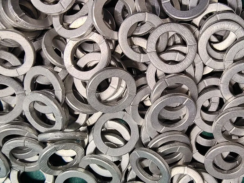
Cold stamping process and tooling design document for double-sided chamfered round washer.
I. Process requirement analysis
1.Product Overview
Double-sided chamfered round washers are critical components in mechanical assemblies, widely used across various equipment types to increase bearing area, reduce friction, distribute load, and prevent leakage. Their key feature is the precise control of diameter, thickness, and uniform double-sided chamfering to specification, which ensures joint integrity and long-term stability under service conditions.
2.Key parameters and requirements
♦ Diameter and thickness: Depending on the application, the washer's OD, ID, and thickness must be held to tight tolerances to meet assembly fit requirements.
♦ Double-sided chamfering: The chamfer dimension (e.g., 0.15 mm) must be consistent across both sides to minimize stress risers during assembly and enhance sealing performance.
♦ Parallelism requirement: Face parallelism directly affects post-assembly flatness and must be held within allowable limits to ensure smooth equipment operation.
♦ Material selection: Choose materials such as stainless steel or copper alloys based on service environment (temperature, pressure, media) to satisfy corrosion resistance, heat resistance, and other performance criteria.
II. Process scheme design
1.Determination of process flow: raw material inspection → cutting/blanking → piercing → double-sided chamfering → deburring → cleaning → inspection → packaging.
2.Selection of chamfering processing method: Cold stamping with dedicated tooling performs simultaneous or sequential chamfering on both faces, balancing cycle time and dimensional accuracy.
3.Setting of quality control points: In-process QC checkpoints are established at cutting, piercing, and chamfering operations, with documented inspection criteria and traceability.
III. tooling Structure Design
1.Overall layout of the toolingDesign the upper and lower tooling stacks. The upper die set carries the pressure plate, punch, and chamfering edge; the lower die set is fitted with the concave die and a locating device to hold the blank in position.
2.Chamfering blade design: Set precise blade angles and geometry to hold the 0.15mm chamfer spec, ensuring consistent edge break on both sides of the washer.3.
Positioning and guidance system: Use precision guide pins and bushings to hold die alignment and repeatability within tolerance across production runs.4.Unloading and ejection mechanism: Design the stripper plate and ejector system so the finished part releases cleanly without distortion or marking.
IV. Materials and Processing Technology5.Tooling material: Specify high-hardness, wear-resistant tool steel like Cr12MoV or SKD11 with good toughness to maximize die life and hold dimensional accuracy over long runs.
6.
Heat treatment: Quench and temper the critical tooling components to bring up hardness and wear resistance while maintaining the toughness needed for stamping loads.7.Processing technology: Machine all tooling components on high-precision CNC centers to hold the required tolerances and surface finish on every detail.
V. Tooling Debugging and Optimization1.No-load tooling test: Run the die set without material to verify fit and alignment of all components, then adjust clearances and settings to the optimal condition.
2.Trial stamping with material: Step up the press tonnage gradually, watch the washer form, and fine-tune die clearance and blade angles until the part meets print.3.
Continuous optimization: Use trial results and production feedback to keep refining the die design and process parameters, pushing up both throughput and part quality.
VI. Production Implementation and Monitoring1.Production planning: Build a detailed schedule from demand forecasts and available press capacity so we hit delivery dates with the right quantities.
2.In-process monitoring: Track the full run—incoming material checks, press condition, process parameters, and finished part inspection—so every step stays in spec.3.
Quality control and traceability: Run a documented QC system with 100% or AQL sampling on finished parts, logging batch numbers and inspection results for full traceability.Continuous optimization: Based on the results of tooling testing and production feedback, continuously optimize the tooling structure and process parameters to improve production efficiency and product quality.
VI.Production Implementation and Monitoring
1.Formulation of production plan: Based on market demand and production capacity, a detailed production plan is formulated to ensure the timely and quantitative completion of production tasks.
2.Production process monitoring: Implementing full-process monitoring, including raw material inspection, equipment status inspection, process parameter recording, finished product quality inspection, etc., to ensure that each step meets the requirements.
3.Quality Control and Traceability: Establish a comprehensive quality management system, conduct full or spot checks on finished products, and record information such as production batches and inspection results to achieve quality traceability.
4.Continuous improvement: We track production data and field feedback on a regular basis, identify process gaps and defects, then implement corrective actions to keep raising both throughput and part quality.