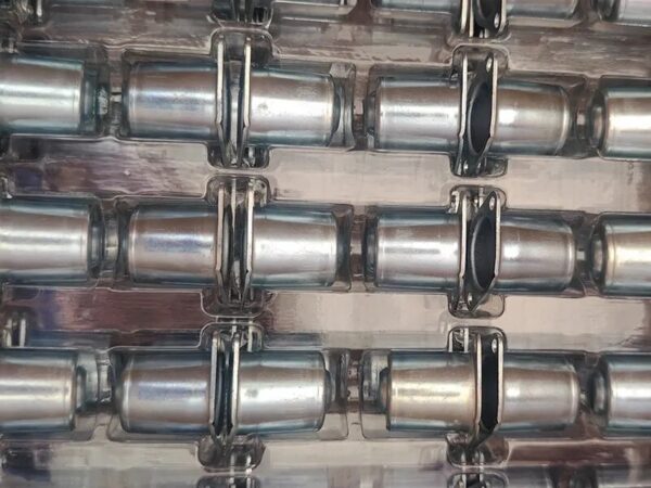
Precision rotary trimming removes excess material from drawn sleeves and housings inside the progressive die.
What is precision in-die rotary cutting?
In-die rotary cutting uses a controlled rotary mechanism to remove excess material from the open end of a drawn cylindrical part. It is commonly applied to sleeves, bushings and housings where a clean, accurately located end face is required.
For suitable parts, Balford can trim a flange-free deep-drawn component directly inside the die. This avoids a separate lathe or secondary trimming station and supports a more energy- and material-efficient production route.
Rotary die structure
A rotary cutting station typically combines a cutting element, drive mechanism, guide components and part-location features. Tool geometry, working angle and cutting path are calculated from the component shape and edge requirement.
Stable guidance prevents lateral movement while the location system controls the part position. The die structure must also manage material flow, cutting load, wear and safe part release.
Controlling edge quality
Edge quality depends on material hardness and ductility, trim allowance, cutting clearance, feed, cutting load and tool condition. Coordinating these variables reduces burrs and distortion and can hold end-face accuracy below 0.10 mm where the component and process permit.
Materials, press and die life
Working components require wear resistance, impact resistance and thermal stability. Alloy tool steels and carbide elements may be selected according to production volume and material. The press and feed system must provide the accuracy and stability needed to keep every station synchronized.
Strip layout and pitch
The strip layout determines material utilization, station loading and production stability. Pitch must accommodate the press stroke, part geometry and rotary mechanism while maintaining enough carrier strength to move the part through each forming stage.
Debugging and production control
During tryout, we verify die installation, clearances, cutting edges, part positioning, and tool wear. Sample inspection results drive adjustments to the die geometry and press parameters before we commit to production runs.
The result is a combined cutting operation that boosts throughput, cuts out secondary machining, and gives you consistent end finishes on deep-drawn round parts.
Discuss Your Component
Need a stable process for a tough metal part?
Send Balford your print, material spec, annual volume, and quality targets. Our engineers will walk through the forming sequence and suggest a practical manufacturing path.
Request a Manufacturing Review