Metal Components for HVAC & Refrigeration Systems
Balford manufactures deep-drawn and stamped metal components for HVAC and refrigeration equipment — temperature sensor housings, solenoid valve parts, IGBT base plates for drive modules, tube assemblies and stamped brackets in copper, aluminum and steel. Production follows ISO 9001:2015 with IATF 16949-aligned quality controls on a 12,000 m² facility with 500+ machines.
What are metal components for refrigeration systems?
Direct answer: Balford manufactures deep-drawn and stamped metal components for HVAC and refrigeration equipment: temperature sensor housings and wells, solenoid valve housings, caps and washers for refrigerant and water circuits, stamped copper base plates for drive IGBT modules, thin-walled tubes, tube assemblies and brackets. Parts are formed on presses of 25–350 t from copper, brass, aluminium and steel, with machining, bending, brazing and assembly in the same plant; plating, passivation and bulk heat treatment are carried out by qualified partners and stated on the quote. Production follows ISO 9001:2015 with controls aligned to IATF 16949, and FAI reports, material certificates and PPAP-level documentation are issued with the order. Sample lead time is 7–15 calendar days for tube bending and machining, and 15–30 days for a single-operation stamping die. What decides whether a refrigeration component works is rarely the outside dimension: it is the sealing surface, the concentricity of the bore and the cleanliness of the joint.
What We Manufacture
Temperature Sensor Components
Deep-drawn sensor housings, wells and connecting pipes for HVAC and refrigeration temperature sensing.
Solenoid Valve Parts
Valve housings, caps and washers for refrigerant and water circuits.
Power-Module Base Plates
Stamped copper base plates for IGBT modules in HVAC variable-speed drives.
Tube Assemblies & Brackets
Thin-walled drawn tubes, tube assemblies, brackets and fittings for system integration.
Why Balford for HVAC & Refrigeration Components
- Processes that fit both copper and aluminum. Deep drawing, stamping and tube forming are run in-house for the copper, brass, aluminum and steel parts HVAC assemblies rely on.
- Sensor and valve housings with sealing in mind. Drawn housings hold concentricity and surface finish where O-rings, seats and sensing elements must seal against refrigerant or water pressure.
- ISO 9001:2015 with IATF 16949-aligned quality management, with PPAP-aligned documentation, FAI reports and material certifications available on request.
- Secondary operations coordinated: nickel plating, machining of sealing faces, tube bending and assembly support for finished sub-assemblies.
Featured Case Studies
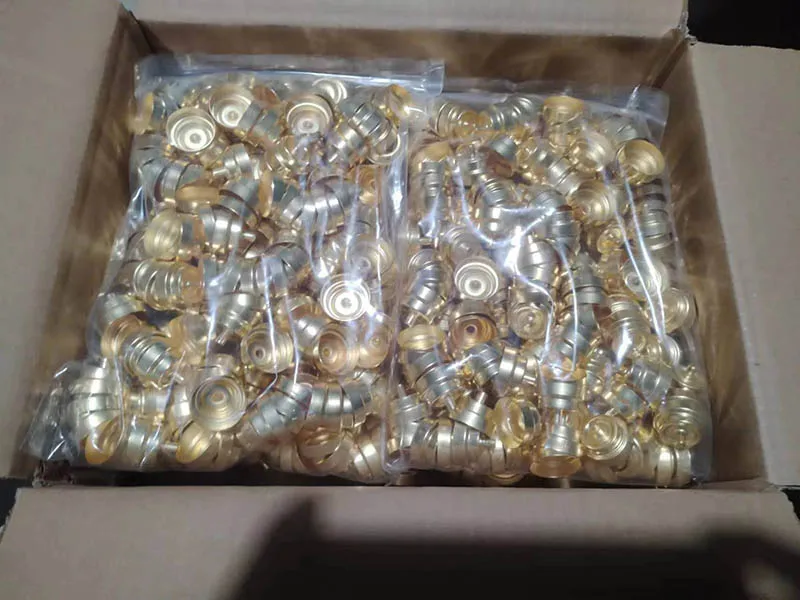
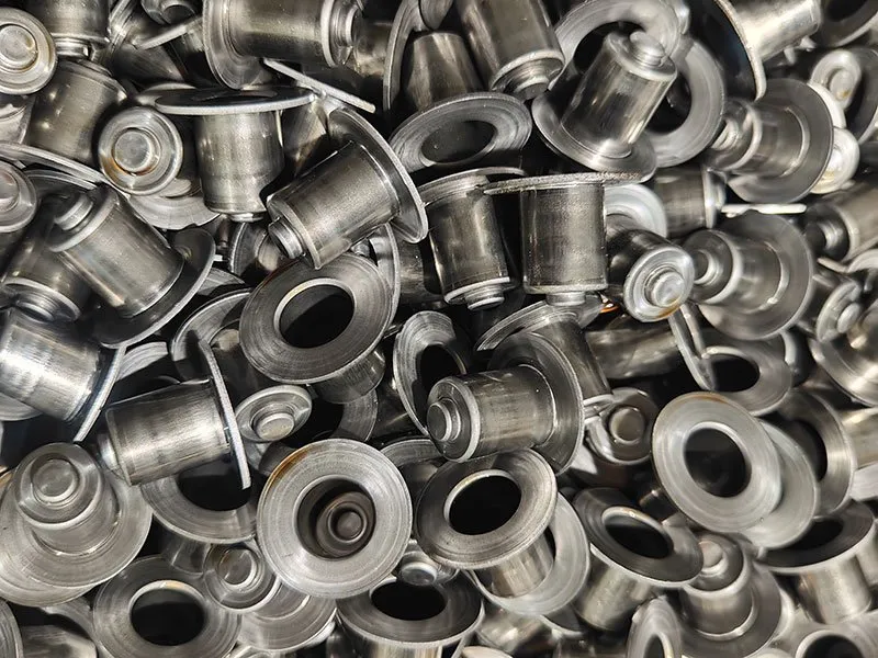
Selected HVAC and refrigeration projects from Balford’s production history. Material, process and application data come from each case record.



Manufacturing Capabilities by Part Type
| Part Type | Typical Process Route | Key Requirements |
|---|---|---|
| Sensor housings / wells | Deep drawing → machining → nickel plating | Sealing surface finish, wall thickness, plating adhesion |
| Refrigerant / water solenoid valve parts | Deep drawing or progressive stamping | Concentricity, clean surfaces, leak-free geometry |
| IGBT / power base plates | Fine blanking → nickel sulfamate plating | Flatness, plating color and stress, dimensional standard |
| Thin-walled tubes & sleeves | Deep drawing / tube drawing | Thickness consistency, roundness, length tolerance |
| Washers, brackets, fittings | Stamping, bending, tube forming | Flatness, parallelism, batch consistency |
Press range 25 t to 350 t; coil-fed progressive lines for high volumes; CNC machining for sealing faces and threads.
Engineering & Quality Considerations
- Pressure-retaining parts are reviewed for burst pressure, wall thickness distribution and leak-path elimination before tooling; drawn housings avoid welds and braze seams where the design allows.
- Corrosion and plating: nickel-plated brass for sensor wells, zinc-nickel where outdoor or condensing environments apply; plating is coordinated with qualified partners and verified on request.
- Temperature range compatibility: materials and plating are selected for the operating range of the loop (refrigerant, chilled water, hot water), and material certificates are provided.
- High-volume consistency: progressive die lines keep dimensional consistency across long runs of washers, brackets and housings used in OEM equipment.
What a refrigeration circuit demands of the metal
HVAC and refrigeration parts fail in ways a general stamping specification does not catch. Five requirements drive the drawing, and each one changes the process route rather than only the dimension.
| Requirement | What the drawing has to state | How it changes the route |
|---|---|---|
| Joint cleanliness | Which surfaces are wetted, and whether the joint is brazed, welded or mechanical | A degrease step is added before the joint is made; drawing lubricant left in a cup burns into the joint and shows up later as a leak or a blocked capillary |
| Sealing surface | The finish and flatness the seal, O-ring or gasket presses against — a dimension alone is not a sealing specification | The sealing face is usually machined after drawing instead of being left as-drawn |
| Bore-to-OD concentricity | Which diameter is the datum, and the concentricity the mating part needs from it | The part is machined in one setup from that datum, or the datum is stated so the fixture can be built to it |
| Wall through the draw | Where the wall is measured, and whether it carries refrigerant pressure | Wall thinning of 10–20% is normal in deep drawing unless ironing or machining is specified, so a pressure-carrying wall cannot be specified at blank thickness |
| Dissimilar-metal contact | Where copper meets aluminium, and whether that joint stays dry, is coated or is isolated | A coating or an isolating washer is added at that interface, or the material pair is changed at DFM |
The refrigerant and the lubricant belong on the drawing for the same reason: HFC and HFO refrigerants and their oils decide what the wetted material has to resist, and an oil that absorbs moisture changes what the part has to survive between brazing and evacuation. Stating the medium is cheaper than discovering it at leak test. How the sensor end of this family is specified is set out on sensor housings; the valve end is covered under solenoid valve housings, and the tube and bracket work under tube assemblies.
Compliance Documents
RoHS and REACH compliance declarations are available for metal components, and material certifications accompany shipments on request. See our RoHS & REACH compliance declaration and quality & certifications pages.
Frequently Asked Questions
Temperature sensor housings and wells, solenoid valve housings, caps and washers for refrigerant and water circuits, copper base plates for drive IGBT modules, thin-walled aluminum tubes, tube assemblies, stamped brackets and fittings.
Yes. Copper, brass, aluminum and steel are processed in-house with dedicated stamping, deep drawing, tube bending and machining equipment; plating and passivation are coordinated with qualified partners.
Yes — CNC machining, surface treatment coordination, tube bending, assembly and leak-test-ready fabrication can be arranged based on your specification.
ISO 9001:2015 quality management with IATF 16949-aligned controls. FAI reports, material certifications and, where required, PPAP-aligned documentation are available on request.
Yes. Prototype tooling is used to validate material, draw ratio and tolerances before production tooling, with a DFM review of your drawing provided up front.
Four things beyond the dimensions: the refrigerant and lubricant the part is exposed to, the finish and flatness of the sealing surface, which surfaces are wetted and have to be clean before a brazed or welded joint, and whether the wall carries pressure. Stating these up front is what lets the process route — as-drawn, machined after drawing, or with a degrease step — be fixed at DFM instead of at leak test.
Drawing lubricant, oxide and handling soil sit exactly where the filler metal has to flow. If they are left in place, the joint looks made but does not wet properly, and the defect appears later as a slow leak or as debris that blocks a capillary. Drawn and stamped parts are therefore degreased before a brazed or welded joint is made, and the drawing should say which surfaces are wetted so the cleaning step covers them.
Have a Drawing or 3D Model?
Send us your 2D drawing or STEP/IGES model. We will review material, tolerances, forming requirements and production volume before quoting.