Balford Die Engineering Service · Zhuji, Zhejiang, China
Stamping Die Design Engineer
Balford pairs senior die designers with an AI-assisted engineering workflow that turns customer drawings into feasible, costed, die-ready designs faster. From drawing intake and DFM risk review to quote, die design, in-house tooling build and PPAP samples, one accountable engineering team owns the die.
What is Balford’s stamping die design engineering service?
Buyers with a stamped or deep-drawn part usually need three decisions answered before tooling starts: can it be made, what will it cost, and how should the die be designed. Balford’s die engineering service answers all three in one workflow.
How the service works
What the engineering review covers
Formability
Draw ratio, single-hit vs multi-stage feasibility, wall thinning and lubrication needs for steel, stainless, aluminium and pure iron.
Tolerances & datums
Critical dimensions checked against realistic drawn-part capability; functional datums and measurement methods defined before tooling.
Tooling risk register
Wrinkles, cracking, springback, hole distortion, burr direction, galling and die-life risks logged with mitigations.
Cost drivers
Material utilization, station count, die size, tool steel, surface finish and secondary machining quantified early.
In-die features
Piercing, forming, tapping and sensor/assembly features sequenced so later operations do not distort earlier ones.
Automotive documentation
FAI, PPAP-aligned documentation and IMDS support planned from project start for automotive part numbers.
Capabilities behind the engineering review
| Capability | What it means for your die | Reference |
|---|---|---|
| Progressive die design & build | Multi-station strip tooling for high-volume stamped parts, including in-die forming, tapping and sensing. | Progressive die stamping |
| Deep-draw die design & build | Single and multi-stage draw tooling for housings, cans, sleeves and sensor shells with controlled thinning. | Deep draw stamping |
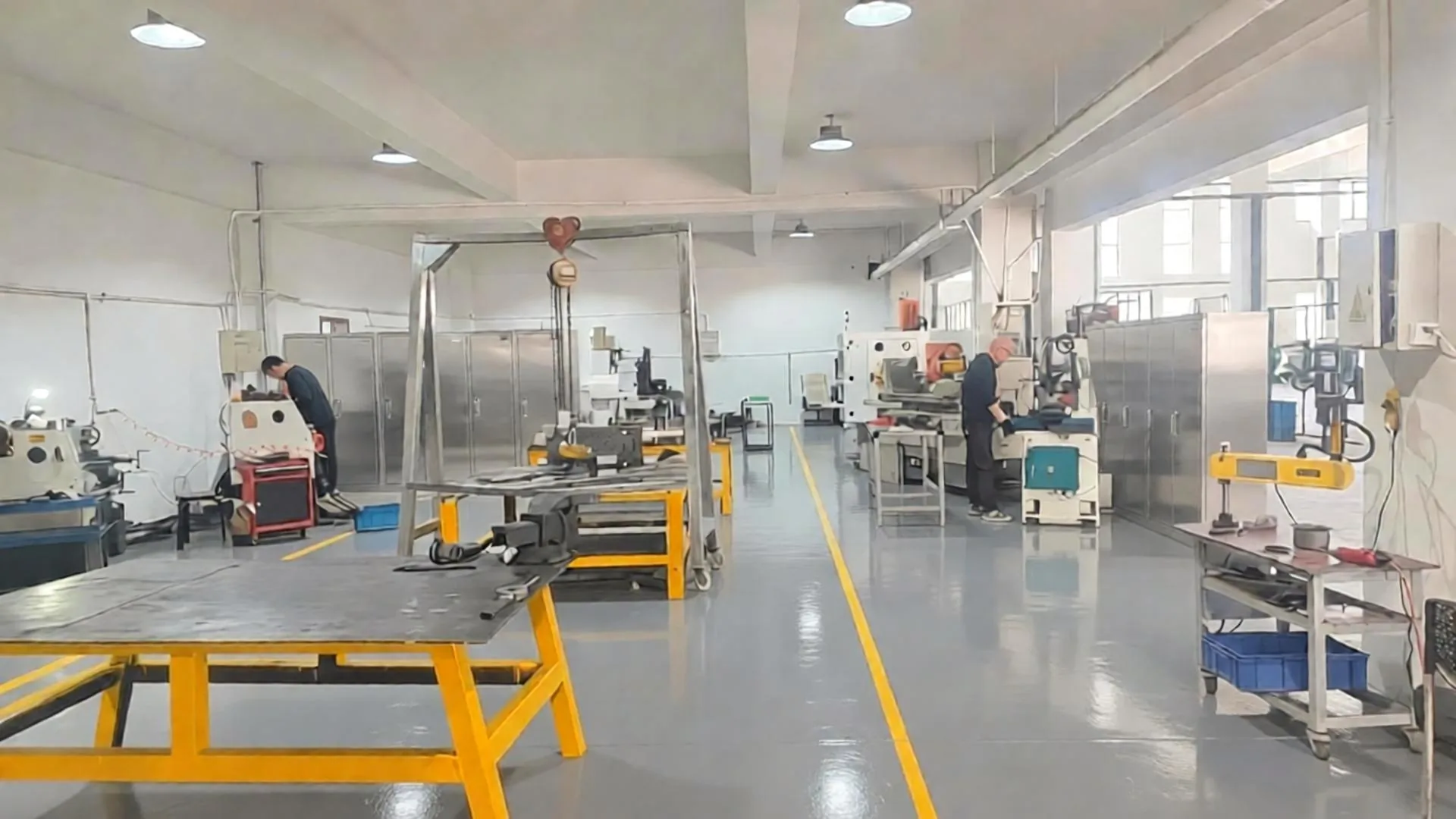
| In-house tool room | Surface grinding, wire EDM, CNC turning/milling, heat treatment and tryout inside the Balford plant. | Tool room overview |
| PPAP & IMDS | FAI, capability studies and material compliance documentation for automotive programs. | PPAP capability |
Engineering estimates in the review are first-pass values confirmed by DFM and tryout. Final die drawings are released by Balford CAD/tooling engineers before manufacturing.
Stamping die design — buyer questions answered
Which files should I send for die design review?
PDF drawings, DXF/DWG, STEP or 3D models work best. Include material grade and thickness, annual volume, PPAP level and any critical tolerance or surface finish notes. Missing items become a short confirmation list instead of assumptions.
How long does a DFM and quotation take?
Balford normally responds within one business day for standard stamped parts; complex multi-stage deep-drawn parts may need an extra day for the tooling concept. Die design and build typically runs 15–30 days after order confirmation.
Do you design and build the die in-house?
Yes. Strip layout or draw sequence, die structure, tool steel selection and BOM are prepared by Balford die engineers, and the tooling is machined, assembled and tried out in our own tool room. Only slow-wire EDM is outsourced, and only for special details.
Can you review parts that need multi-stage deep drawing?
Yes. Multi-stage deep drawing is a core Balford capability for solenoid valve housings, sensor housings and motor parts. The review defines each redraw, checks cumulative thinning and flags intermediate annealing when needed.
Do you provide PPAP samples and documentation?
Yes. Dies are tried out on Balford production presses, first articles are inspected in-house, and PPAP-aligned documentation plus IMDS data can be prepared for automotive part numbers.
What if my part is not suitable for stamping or deep drawing?
The review will say so directly and suggest an alternative: CNC machining, sheet metal fabrication or a design change that makes the part formable. We do not push parts into a process that will fail.
Start with a free DFM review
Send your drawing and target volume — Balford’s die engineering and sales team normally responds within 24 hours with a feasibility opinion and production quote.
Read: Top-tier stamping die design — 13 checkpoints buyers should expect