Summary
The features that decide whether a deep drawn housing works - internal fillet radii, total runout and concentricity - are usually the ones no gauge can reach. The accepted routes are destructive sectioning with optical projection for internal radii, an expanding mandrel with a dial indicator for runout, and CMM for concentricity on a defined sample count. This guide sets out each method, the acceptance criteria, the sequencing around heat treatment, and the uncertainty that has to appear on the report.
Why the critical features are the ones you cannot reach
A deep drawn housing is a closed shell, and the dimensions that decide whether the part functions sit inside the geometry that forming created. An internal fillet radius controls how the wall thins as material flows over the punch nose. The total runout of a bore decides whether a plunger seats squarely. Concentricity between an inner and an outer diameter formed in two different operations decides whether the assembly aligns. A radius gauge, a caliper or a micrometer needs contact on both sides of the feature and a sightline to confirm the contact is correct. Inside a 12 mm bore that is 30 mm deep, there is neither.
The consequence is that unreachable features get handled differently from reachable ones. A diameter gets measured on every sample because it is easy. An internal radius gets estimated, copied from the previous revision of the report, or signed off because the sample looks right under the bench light. The fix is not a better instrument. It is a written method for each feature, agreed before the first sample is measured, and an uncertainty stated next to the result. Our own documentation runs on an ISO 9001:2015 quality system with IATF 16949-aligned controls, and the inspection plan is where that system holds together or does not.
A method map for features no gauge can reach
Before writing an inspection plan, it helps to fix the method for each unreachable feature and to write down how good that method is. The table below is the version we use internally.
| Feature type | Why a gauge cannot reach it | Accepted measurement method | Stated uncertainty |
|---|---|---|---|
| Internal fillet radius on a drawn shell | The blade of a radius gauge cannot be seated inside the bore, and the arc blends into the blend left by the previous draw | Section the part through the plane containing the radius, polish the section, project it optically at 10x to 20x and compare against the drawing radius | About plus or minus 0.10 mm on the radius when the cut is confirmed on the centre plane; wider and biased low if the cut is off-centre |
| Total runout of an inner diameter | No instrument available locally can hold the datum and sweep the whole surface | Part fixed in a lathe chuck on an internal expanding mandrel, inner diameter swept with a dial indicator | Indicator resolution 0.01 mm; a measured value of about 0.07 mm inner-diameter runout. True total runout is larger, because runout is one component of it |
| Concentricity of inner to outer diameter | Both diameters are formed in separate operations and cannot be swept together with hand tooling | CMM with a declared datum scheme, a fixed sample count, and the treatment state of the samples stated | CMM accuracy of a few micrometres plus fixturing repeatability; the number is meaningless without saying whether the part was heat treated |
| Bore depth referenced to a face | A depth micrometer cannot reach past an internal shoulder without tilting | Height gauge on a surface plate, part stood on its reference face, using the customer's own method | 0.02 to 0.05 mm depending on face flatness and on burr at the reference edge |
| Burr height at a leak-critical seat | The burr is at the edge of an internal feature and is smaller than the resolution of hand tooling | Assess at 10x magnification with a toolmaker's microscope or comparator against the agreed limit | The limit of the check is the resolution of the magnification used; a caliper at 1x will read zero and prove nothing |
| Wall thickness in the drawn wall | A micrometer anvil cannot be placed squarely on a curved, thinned wall without deforming it | Ball-anvil or pointed-anvil micrometer on the formed wall, or a measured section if the part is being cut anyway | 0.01 mm for the instrument, plus sectioning distortion when the destructive route is used |
Internal radii: section the part and project it
The accepted answer for internal fillet radii on a drawn shell is destructive sectioning plus optical projection. Cut the part through the plane that contains the radius, mount and polish the section, then measure the arc on an optical projector at magnification, against an overlay or by direct reading. In a real case from our own files, a drawing carried four R angles and three of them were on the inner diameter; no radius gauge in the tool crib would reach them, so the parts were sectioned and the radii read on the projector. The customer accepted the method, because it was named in the inspection plan before it was used rather than offered as an excuse afterwards.

Sectioning is only defensible if three conditions are met before the first cut is made. A first is that the method is named in the inspection plan and acknowledged by the customer, so sectioning reads as an agreed technique instead of an admission that the feature was never controlled. A second is that the cut plane is defined on the drawing or in the plan: a section taken half a millimetre off the centre plane reads a chord rather than the radius, and a chord reads small, typically 10 to 20 percent low for a shallow fillet in a 12 mm bore. A third is that the sample count is fixed and stated, because every section destroys a part. Use a spare from the same lot rather than consuming the qualification sample that has to be retained.
Acceptance should be written as two clauses. First, the projected arc lies inside the drawing tolerance when compared against the calibrated overlay. Second, the section is confirmed to be on the defined plane, checked by comparing wall thickness on both sides of the cut; if they differ by more than about 0.05 mm the cut is off-centre and the radius reading should be discarded.
Runout: an expanding mandrel, a lathe and a dial indicator
Runout is harder, because the callout assumes a datum system and a full sweep that a hand tool cannot provide. In one case the shop could not find a suitable instrument locally, so the sample was fixed in a lathe chuck on an internal expanding fixture - a mandrel that grips the bore from the inside - and the inner-diameter runout was swept with a dial indicator. The reading was approximately 0.07 mm. That number is not the total runout. Total runout includes runout as one of its components, and such a sweep captures the behaviour at the measuring station rather than the whole surface, so the true value is somewhat larger.
The report should carry the number, the method and the limitation in the same line: measured 0.07 mm inner-diameter runout, dial indicator, part held on an expanding mandrel in a lathe chuck; total runout was not measured directly and is expected to be larger, because runout is one component of it. That single sentence is worth more than a clean number, because it tells the reviewer exactly what the figure can and cannot support. Presenting the figure as though it came off a CMM is the mistake; it usually survives one review and then fails the first functional test.
Where a mandrel measurement loses accuracy
Four error sources stack up in a mandrel check, which is why the uncertainty has to be stated. Mandrel-to-bore clearance appears directly in the reading, so a 0.02 mm fit contributes up to 0.02 mm of apparent runout. A part not fully seated on its datum face reads squareness as well as runout. Chuck jaws can introduce ovality in a thin wall, so light clamping matters more than a rigid setup. And the stylus reads draw marks as surface texture. A mandrel check therefore bounds the part rather than characterising it.
Concentricity by CMM, and the heat-treatment trap
Concentricity is genuinely measurable on a CMM, and here the instrument is rarely the problem. The sequence is. In one case a first CMM concentricity check showed parts out of tolerance, and the cause was not the die. It was heat treatment moving the part between forming and final measurement. The fix was process rather than metrology: the machining was split into two operations to reduce the effect of heat treatment on concentricity, and a second CMM check taken before heat treatment then met the drawing. That is the trap in one sentence - pre-treatment data can look excellent on a feature that fails after the furnace. The heat treatment step in the process route is therefore part of the measurement plan.
Two consequences follow for anyone writing an inspection plan. State on every concentricity line whether the sample was measured before or after heat treatment, because the two numbers describe different parts. And fix the sample count before the first measurement, since concentricity varies with coil position and with tooling condition. A three-sample check from the start of a run tells you about the die, not about the lot.
Sequencing rule: what to measure before heat treatment and what after
The rule is simple: anything heat treatment or a secondary operation can move must be accepted on post-treatment data, while anything describing the forming geometry is best measured before treatment when the purpose is to diagnose the die. Mixing the two produces false failures, where a good part is rejected on the wrong measurement, and false passes, where a bad part is accepted on a pre-treatment number.
| Feature | Before heat treatment | After heat treatment | Why the order matters |
|---|---|---|---|
| Draw radii and formed diameters | Yes - this is the forming signature | Yes, for final acceptance | The pre-treatment value tells you whether the die is correct; the post-treatment value tells you what was shipped |
| Concentricity of inner to outer diameter | Yes, as a process check | Yes - only post-treatment data can accept the part | Heat treatment moves the part, so an excellent pre-treatment reading can mask a post-treatment failure |
| Total runout | Yes, to catch a die or fixturing problem early | Yes, as the acceptance number | Runout grows through annealing; reporting the pre-treatment value as the acceptance value is a false pass |
| Internal fillet radius by sectioning | Optional | Preferred | Each section destroys a part, so cut the one that represents the delivered condition |
| Burr height at a leak-critical seat | Yes | Yes, after every secondary operation | Deburring and tumbling change burr height in both directions; a pre-tumble pass is not evidence of a post-tumble pass |
| Hardness and microstructure | No | Yes | Only meaningful after the treatment cycle has been completed |
One related caution concerns wall condition. Ironing and annealing interact with surface finish and with the wall thickness tolerance you can hold, and both change what a section shows. Where the drawing couples a radius to a surface requirement, the limits ironing can hold on tolerance and finish should be read together with the radius callout rather than treated as unrelated notes.
Go/no-go gauges and checking fixtures belong to the tooling package
Fixtures and gauges - go and no-go - normally sit inside the tooling package rather than in a separate metrology purchase. This matters because buyers frequently assume a tooling quotation covers only the die, and then treat gauging as an extra to be negotiated later. A checking fixture built alongside the die shares its datums, arrives with the first samples, and is the cheapest reliable way to control a production feature no universal instrument can reach. When a callout will be gauged at 100 percent in production, the go/no-go gauge should be named in the tooling list and in the control plan, with its own calibration record and wear check interval.
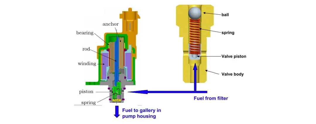
For parts where these callouts cluster - bores, internal seats and shoulders - it also helps to know where the process can hold the dimensions at all. Our published capability boundaries set out the tolerances we will commit to on drawn diameters, wall thickness and length, and solenoid valve housings are the family where an internal seat most often carries a radius, a runout and a leak requirement at once. Wall thickness and radius also drive forming load, which the deep draw force calculator estimates before the die is cut.
Burr height at 10x where the surface is leak-critical
On a ball seat inside a drawn housing, sealedness is often achieved by the absence of tool marks rather than by any separate seal. The region that holds the steel ball has an airtightness requirement, and the acceptance rule that goes with it is that no drawing line is visible at 10x magnification. Burr height at that edge is not cosmetic, because a burr of a few micrometres is enough to lift the ball off its seat. The method is a toolmaker's microscope or comparator at 10x against an agreed limit, and the magnification used has to be recorded on the report. A burr inspected at 1x reads zero and proves nothing about the leak test.
Real measured data: sample size, gauge per feature, balloon order
Buyers audit data honesty, and they are usually right to. A reviewer has said outright that they believed some dimensions in a ten-sample report had not actually been measured. Filling a report from the nominal is quick, invisible in the document, and eventually exposed by a functional failure or by a second source measuring the same feature. The discipline that prevents it is unglamorous: every line carries the gauge, the sample count and the balloon number, so a reviewer can trace any value back to an instrument.
- Sample size, stated per feature. A full-dimensional report on 10 samples is the common requirement; when a destructive method is used, the section count is smaller and must be declared, for example 3 of 10 parts sectioned for internal radii.
- Gauge identification per feature, in the report body rather than only in a calibration file. Section-and-projector rows and CMM rows must be distinguishable at a glance.
- Balloon numbering order in the customer's numbering, not the shop's convenience order, so that the same balloon number refers to the same feature across drawing revisions and two revisions can be compared line by line.
- No nominal fill. If a feature was not measured, the cell says so and gives the reason and the alternative method used, rather than carrying a plausible number.
- Unit convention stated once and applied throughout. Some customers require imperial units with the conversion done in-house; a mixed report is a reading error waiting to happen.
Getting these five conventions into the first submission also shortens the approval loop, because the reviewer is not stopped by gaps. The same conventions are set out in the guide to engineering drawings for deep drawn parts, which covers how a callout should be written so that a method exists for it, and they are among the checks a buyer runs when evaluating a stamping supplier against a sample report.
Method matching and calibration: two failures worth avoiding
Two failure modes cut across all of the methods above. The first is method mismatch. A bore depth referenced to a shoulder can be checked with a depth micrometer or with a height gauge on a surface plate, and the two readings differ by an amount set by burr and face flatness at the reference edge. In one case depth was deliberately verified with a height gauge to match the customer's own method, so that the numbers could be compared directly. Where the customer's method is known, match it and say so on the report.
The second is calibration trust. A calibration house was once identified as questionable because its width measurements disagreed with repeat measurements taken in-house on the same parts. The chain from instrument to certificate to the method the drawing assumes is only as strong as its weakest link, and a certificate does not correct a method that was never agreed. Where two sources disagree on a simple width, the disagreement is a signal about the calibration route, not about the part.
Related reading on deep drawn stamping
These companion notes go deeper on the same engineering decisions:
- DC01 vs DC04 vs SPHC vs SPHE: Which Grade?
- How Many Draw Steps Does a Part Need?
- Tightening a Tolerance: What It Costs in Tooling
- Drawing Lines, Die Marks and Galling on Drawn Parts
FAQ: FAQ: Inspecting Internal Radii, Runout and Concentricity on Deep Drawn Parts
Q: How do you measure an internal fillet radius inside a deep drawn housing?
A: Section the part through the plane containing the radius, polish the cut face and measure the arc on an optical projector at 10x to 20x against an overlay or by direct reading. This is a destructive method, so it has to be written into the inspection plan and covered by a declared number of sections. Results are meaningful only if the cut is confirmed to be on the centre plane, which is checked by comparing wall thickness on both sides of the section.
Q: Can total runout be verified without a CMM or a dedicated runout fixture?
A: A workable approximation is to hold the part in a lathe chuck on an internal expanding mandrel and sweep the bore with a dial indicator. A measured inner-diameter runout of about 0.07 mm was obtained this way in one case, but it should be reported with its limitation: total runout includes runout as a component and a single-station sweep does not capture the whole surface, so the true value is somewhat larger. Report the method and the uncertainty together.
Q: Should concentricity be measured before or after heat treatment?
A: Both, but only the post-treatment result can accept the part. Pre-treatment CMM data can meet the drawing while post-treatment data on the same feature is out of tolerance, because annealing moves the part. Where that happened, the fix was to split the machining into two operations and re-check before heat treatment, after which the drawing was met. State the treatment state on every concentricity line.
Q: Are checking fixtures and go/no-go gauges included in tooling cost?
A: In our quotation structure they are part of the tooling package, not a separate metrology purchase. A checking fixture is built around the same datums as the die, so it is available when the first samples are, and a go/no-go gauge named in the control plan is the most economical way to control a production feature that no universal instrument can reach. Ask for the gauge list and the calibration plan with the tooling quotation.
Q: What uncertainty should appear on a dimensional report for an unreachable feature?
A: Enough to let the reviewer judge the result: the instrument, the method, the sample count and the direction of the known error. Sectioned radii carry roughly plus or minus 0.10 mm when the cut is on the centre plane. Mandrel runout carries the indicator resolution plus the mandrel clearance, and is a lower bound on total runout. CMM values carry the machine accuracy plus fixturing repeatability. A number without this context is not a measurement, it is an assertion.
Q: Why is burr height measured at 10x magnification on a drawn seat?
A: Because on a leak-critical ball seat sealedness depends on the absence of tool marks, and a burr of a few micrometres can lift the ball off its seat. At 1x with a caliper the reading is effectively zero. At 10x, a toolmaker's microscope or comparator resolves the edge against an agreed limit, and the acceptance rule can be written as no drawing line visible at 10x. Record the magnification on the report so the check is reproducible.
Q: How many samples should a full-dimensional report cover?
A: Ten samples is the common requirement, with the drawing ballooned and the report lines numbered in the customer's balloon order so revisions stay comparable. Where a method is destructive, fewer parts can be measured, and the report must state the reduced count explicitly, for example 3 of 10 sectioned. Every line should name the gauge used, because buyers check whether the data was actually measured rather than copied from a nominal.