Summary
Tightening a tolerance on a deep drawn part does not scale the way loosening one does. A band of ±0.05 mm on a drawn diameter is a process tolerance the draw itself can hold; ±0.02 mm is a different operation, usually sizing or coining, and it arrives with an extra station, consumable inserts, a slower stroke rate, more frequent die maintenance, heavier inspection and a higher reject rate. This article sets out the confidence ladder used on the shop floor, the arithmetic that turns two tight diameters into a tight wall, and how to decide which dimensions are worth the cost.
Reading a Tolerance the Way a Tool Shop Reads It
A tolerance on a drawing is a statement about a manufacturing process the drawing author has usually not yet chosen. On the shop floor a callout is read against a short ladder of bands, and the band decides what the tool must contain.
General dimensions on a drawn or stamped part sit near ±0.25 mm. A diameter the draw controls directly holds ±0.05 mm, and that is the band we will sign without a caveat. The same feature called out at ±0.15 mm reads differently: it is looser than the process needs, so an engineer concludes the author did not know what the feature has to do, because a functional dimension is rarely drawn several times looser than the die holds. ±0.02 mm is a third case and needs a caveat about which dimensions it can even apply to. Those bands are published as our capability boundaries.
| Callout on a drawn diameter | How it reads on the shop floor | What it implies about the requirement |
|---|---|---|
| ±0.25 mm, general block | A normal drawn or stamped dimension | No specific assembly function, so the general block is sufficient |
| ±0.15 mm | Looser than the draw process naturally holds | The author had no clear functional requirement, so the number was estimated or inherited from an earlier revision |
| ±0.05 mm | The band a controlled draw holds routinely | The feature locates, seals or fits something, and the drawing knows it |
| ±0.02 mm | Outside what drawing alone controls | The feature needs sizing, coining or machining, and it must be reachable by a gauge |
The ±0.15 mm row is the most avoidable of the three: easy to meet, but close enough to a functional band that the tool designer has to ask what the feature does, and far enough from the general block to look deliberate. Either tighten it to a band the process controls, or release it to general tolerance.
Why ±0.02 mm Is Not a Tighter Version of ±0.05 mm
Tightening does not scale the way loosening does. ±0.05 mm is a process tolerance: punch, die bore, strip thickness and draw sequence together produce a distribution inside a 0.10 mm window when the tool is designed and maintained for it. ±0.02 mm is a 0.04 mm window, and at that width the draw is no longer the thing being controlled. Strip thickness variation, lubrication, springback, die wear and thermal drift all remain, and none is removed by polishing a die, because they are properties of forming rather than of tool precision.
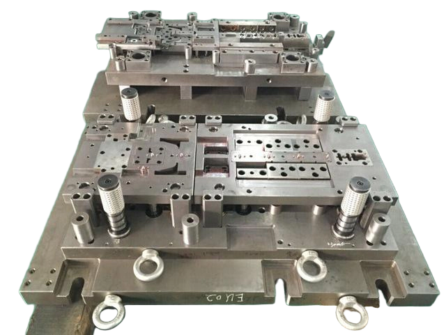
What ±0.02 mm requires is a second operation: a sizing or coining station closing hardened surfaces on the feature after the final draw, so the material is forced to a dimension instead of arriving at one; sometimes an ironing pass; occasionally a machining operation, after which it is no longer a stamping tolerance at all. Each route brings a station, an insert and a maintenance interval that stamping die design has to absorb at the layout stage.
There is also a measurement precondition that is often skipped: a ±0.02 mm callout is meaningful only if a gauge can reach the feature and resolve it. A wall thickness inside a 12 mm bore, a radius blending into the fillet of the previous draw, a diameter interrupted by a slot: in each case the measurement uncertainty is a significant fraction of the band.
The Arithmetic That Catches People Out: Half-Bands Add
Two tight diameter callouts on one drawn feature do not give two independent dimensions. They give a tight wall, whether the drawing says so or not, because the wall is half the difference between the diameters and each half-band passes straight through into it. The full allocation between inner diameter, outer diameter and wall is worked through in the separate note on that trade. Take an outer diameter of Ø10.00 ±0.05 mm and an inner diameter of Ø9.00 ±0.05 mm on a nominal 0.5 mm wall.
- Thickest wall, outer diameter high and inner diameter low: (10.05 − 8.95) / 2 = 0.55 mm.
- Thinnest wall, outer diameter low and inner diameter high: (9.95 − 9.05) / 2 = 0.45 mm.
The wall therefore carries a 0.10 mm spread, which is ±0.05 mm about nominal, exactly the sum of the two half-bands: 0.05 + 0.05. On a 0.5 mm wall that is ±10 percent of the wall thickness, and it must hold at every point around the circumference and along the drawn length. The arithmetic also runs backwards, which is more useful while a drawing is still open: a wall of 0.50 ±0.08 mm permits 0.16 mm of combined diameter half-band, and how that is split between the two diameters is a design decision.
What Tightening Costs, Line by Line
A tight tolerance is expensive not because of the number itself, but because of what must exist in the tool and in the control plan for the band to repeat over a production life rather than on a submission sample. A sizing station is the clearest item, and only the first.
A sizing or coining station is an added stage in a progressive or transfer die, with its own inserts, tonnage demand and alignment relative to the stations before it. Working the material twice consumes insert life faster than a forming station, so more consumable inserts are held and more die maintenance is scheduled. A coining station commonly means a slower stroke rate, because it needs dwell or reduced speed to set the dimension instead of letting it spring back. Such a band is rarely accepted by sampling, so inspection frequency rises and the feature often moves to 100 percent gauging. A narrower window around an unchanged process centre also rejects more parts, because the spread stays while the band shrinks.
| What tightening adds | Where it lands | What it changes over the life of the program |
|---|---|---|
| An extra sizing or coining station | Die design and build, station count, press tonnage | A longer die, one more alignment and wear point, more to maintain |
| More die inserts, treated as consumable | Tooling spares and die maintenance budget | Shorter insert replacement intervals for the whole program |
| Slower stroke rate | Press output and scheduling | Lower capacity per press hour on that part number |
| More frequent die maintenance | Planned and unplanned downtime | More grinds, more requalification, more first-off checks |
| Higher inspection frequency | Control plan, gauges, inspection labour | Sampling gives way to 100 percent gauging, which needs a fixture and its own calibration |
| Higher reject rate at unchanged process spread | Material, press time and yield | Scrap and rework become a standing line rather than an exception |
None of these items is a reason to refuse a tight tolerance. They are the reason a tight tolerance belongs on a feature that needs it. Moving tolerance off a dimension that merely came out of a CAD model and onto one that locates, seals or closes a magnetic circuit is where the economy of a stamped part is decided.
Formed, Coined or Machined: Three Different Claims
The same number means three different things depending on the surface it sits on. A formed surface is produced by material flow, so its band is set by the process. A coined surface is produced by forcing metal between hard surfaces after forming, so its band is set by the tool. A machined surface is produced by removing material, so its band is set by the machine and the setup. A drawing that puts ±0.02 mm on a formed surface and ±0.05 mm on a machined shoulder has them the wrong way round.
| Feature type | How the dimension is produced | Band that holds in production | How it should be quoted |
|---|---|---|---|
| Formed diameter or depth | Punch, die bore and material flow across the draw sequence | Around ±0.05 mm on a controlled draw, wider on deep or thin-walled features | As part of the stamping process, with the draw sequence and material called out |
| Coined or sized diameter, flat or step | Hardened surfaces closing on the feature after the final draw | Down to roughly ±0.02 mm, subject to a capability study on the actual geometry | As a separate sizing operation inside the die, with its own station and inserts |
| Machined bore, face or step | Turning, milling, drilling or grinding after forming | Set by the machine and the setup, typically tighter than the draw can hold | As a secondary machining operation, quoted separately from the stamping |
| Wall thickness in the drawn shell | Material between punch and die, plus ironing where it is used | Around ±0.08 mm on a 0.5 mm wall is a realistic planning band | Explicitly, as a wall callout with a defined measurement plane |
Two consequences follow. A tight callout on a formed surface should move onto a coined surface wherever function allows, because that converts an unstable process requirement into a stable tool requirement; an ironing pass does the same for dimensions coupled to wall thickness, with surface finish negotiated alongside ironing tolerance and surface finish.
Second, if a feature genuinely needs machining, say so on the drawing and expect it to be quoted as a machining operation. A tolerance that silently assumes a machining step is discovered at first article, and the argument that follows is about intent rather than capability.
General Tolerance Blocks and the Dimensions Nobody Calls Out
Almost every drawing carries a general block, most often GENERAL DIMENSIONS ±0.25 mm with a note that dimensions without an individual tolerance fall under it. On a bent or blanked part that is a fair description of the process. On a deep drawn part it should be read with care, because the dimensions that fall under it are not the easy ones.
Angular dimensions, radii, heights taken from a formed face and the position of a pierced hole relative to a drawn wall are frequently left uncalled-out, and that is where surprises sit. When such a dimension arrives 0.3 mm off nominal, no agreed rule says whether the part is good, so acceptance is settled by whoever happens to inspect it.
Where the general block gets misread: GENERAL DIMENSIONS ±0.25 mm covers dimensions that were not individually toleranced, not dimensions that are unimportant. A hole position, a flange height after a redraw, the flatness of a coined weld face or a radius that controls material flow should never be left to the general block, even though the block will technically receive them.
Reference callouts carry the same caution. Marking a dimension as reference removes it from the acceptance argument, which is useful only when the shop is told which dimension is actually controlled. A drawing that marks both the diameter and the wall as reference leaves nothing to inspect, which is the state the conventions for callouts on a deep drawing exist to prevent.
Cpk Thinking and Every-Part-In-Band Are Both Reasonable
A supplier and a buyer can look at the same data and disagree about whether a process is capable, without either being wrong. The supplier usually reasons statistically: if the process centre sits on nominal, the spread is stable and the calculated capability index is comfortably above the usual acceptance level, then the process is capable and parts at the edge of the band are normal distribution behaviour.
The buyer frequently reasons absolutely: every dimension of every part must be inside the band, because an assembly station sees the parts in front of it, not a distribution. The practical difference is the width of the band relative to the natural spread. When the band is several times the spread the two views agree; when the band is close to the spread, the statistical reading says the process is fine while the absolute reading says a predictable fraction of parts will fail. The remedy is a wider band or a narrower process, at very different cost. A capability figure quoted without its sample count and gauge belongs nowhere near the quality documentation a buyer audits.
Two conventions keep this argument short: state whether acceptance is statistical or absolute on the drawing or in the control plan, and when it is absolute, give a band an absolute reading can meet.
The Decision Table: Band, Requirement, Cost, Realism
The table below puts the band, what it forces into the tool, its relative cost and whether it is realistic on each feature category on one line, so the decision is taken with its consequences visible.
| Band on a diameter | What it requires | Relative cost and control | Formed feature | Coined feature | Machined feature |
|---|---|---|---|---|---|
| ±0.25 mm | Nothing beyond the normal draw sequence and the general block | Baseline; sampling inspection is usually adequate | Yes | Yes | Yes |
| ±0.15 mm | A controlled draw with normal tool maintenance | Close to baseline; no added station | Yes, but the callout carries no functional information | Yes | Yes |
| ±0.05 mm | Die and punch held in a narrow band, strip thickness controlled, wear monitored between grinds | Higher: tighter tool maintenance, more inspection, some reject risk at the band edges | Yes on a controlled drawn diameter with a declared draw sequence | Yes | Yes |
| ±0.02 mm | A sizing or coining station after the final draw, or a machining operation, plus a gauge that can reach the feature | Highest: extra station, consumable inserts, slower stroke rate, more maintenance, often 100 percent gauging | No, not by drawing alone | Yes, with a capability study on the actual geometry | Yes, but it is a machining tolerance and should be quoted as one |
Read the last three columns together with the two before them: the band does not set the cost on its own, the feature category does. A ±0.02 mm band on a coined step is a routine tool requirement, while the same band on a formed diameter asks for a process the draw does not possess. That is why a supplier may accept one ±0.02 mm callout on a sheet and decline another on the same sheet without being inconsistent.
The Conversation That Settles It: Functional Versus Modelled
Most over-tight tolerances do not come from unreasonable engineers. They come from models. A CAD model carries every dimension at full precision, and unless someone deliberately decides which dimensions affect assembly, sealing, fit or the magnetic circuit, the drawing either inherits that precision or receives arbitrary bands.
- List the dimensions that touch something else: bores that receive a piston, spool or insert; diameters pressed into a housing; faces that carry a seal or a weld; steps that set an air gap in a magnetic circuit.
- For each one, write the failure mode if it drifts. A leaking seat, a loose press fit, a spool that sticks, an air gap that shifts the force curve. A dimension with no describable failure mode is not functional.
- Assign the band from the failure mode rather than from the model, using the arithmetic that links the feature to the wall or to the stack it belongs to.
- Move everything else to the general block or to a reference callout, and accept that the shop will use that slack where it helps the critical features.
- Name the measurement for each functional dimension, because a tight band that cannot be gauged repeatably will be argued about at every lot.
The fourth step is the one that pays. A clearance diameter opened from ±0.05 mm to ±0.15 mm, an internal relief moved to general tolerance, a non-critical flange height left free: each gives the tool room for the dimensions that matter. Repeated housing families also show which callouts normally carry a real requirement, as the deep drawn solenoid valve housing family makes clear.
When We Decline to Quote a Tolerance
The honest position is that a tolerance we cannot hold should be refused rather than accepted and then missed. A refused callout starts a technical conversation while the drawing is still open: which feature is functional, whether the band can move onto a coined or machined surface, whether a different measurement or assembly clearance would satisfy the requirement. A number accepted to keep a quotation moving produces the same conversation after the die is cut.
The cases are narrow and recognizable: a ±0.02 mm band on a formed surface with no sizing station and no gauge access; a tight diameter combined with a tight wall on a feature that cannot be sized or machined afterwards, where the stack has already made the requirement self-contradictory; a band tighter than the incoming strip thickness tolerance on a dimension that inherits strip thickness directly. In each case we offer the achievable band, the feature it applies to and the operation that would be needed to go tighter. Stating a limit is not a weakness in a quotation.
Related reading on deep drawn stamping
These companion notes go deeper on the same engineering decisions:
- Deep Drawn Housing Wall Thickness Tolerance: ID, OD and Wall
- Deep Drawn Stainless Steel Cracking: A Root-Cause Ladder
- Plating a Deep Drawn Housing: Thickness vs the Tolerance Budget
- The Deep Drawing DFM Checklist Before Cutting Steel
FAQ: FAQ: What Tightening a Tolerance Costs on a Deep Drawn Part
Q: Does tightening a tolerance on a deep drawn part just mean a better-made die?
A: No. A better die removes the error that comes from tool precision, but a band of ±0.02 mm sits outside what the draw process controls at all. What remains is strip thickness variation, lubrication, springback, die wear and thermal drift. Reaching ±0.02 mm normally means adding a sizing or coining station after the final draw, or moving the feature to a machining operation, and either route changes the tool, the station count and the control plan rather than only the die quality.
Q: What does a ±0.15 mm callout on a drawn diameter tell a tool shop?
A: That the requirement was never defined. The band is wider than the draw process naturally holds, so it is easy to meet, but it is also far enough from the general block to look deliberate. The tool designer then has to ask what the feature does. A drawing is usually better with that dimension either tightened to ±0.05 mm because it is functional, or released to general tolerance because it is not.
Q: How do two tight diameter tolerances turn into a tight wall tolerance?
A: The wall is half the difference between the diameters, so each diameter half-band passes through into the wall and the two add. An outer diameter of Ø10.00 ±0.05 mm with an inner diameter of Ø9.00 ±0.05 mm gives a wall from 0.45 mm to 0.55 mm, a spread of 0.10 mm on a 0.50 mm nominal wall. Converting the callouts back from a wall requirement is the more useful direction, because it fixes the combined diameter budget before either diameter is chosen.
Q: What is the difference between a tolerance on a formed surface and on a coined one?
A: A formed surface is produced by material flow, so its band is limited by the process and settles around ±0.05 mm on a controlled drawn diameter. A coined or sized surface is produced by forcing metal between hardened surfaces after forming, so its band is set by the tool and can reach roughly ±0.02 mm on suitable geometry. The same number on the drawing therefore describes a routine tool requirement in one case and a process the draw does not have in the other.
Q: Why does a tighter tolerance raise the reject rate even when the process has not changed?
A: Because the process spread is unchanged while the acceptance window shrinks. If the distribution of a dimension stays the same and the band around nominal narrows, a larger fraction of parts falls outside the band. That is arithmetic, not a decline in workmanship. It is also why a tightening request is worth examining feature by feature: the cost is only justified on dimensions that affect assembly, sealing, fit or the magnetic circuit.
Q: What does GENERAL DIMENSIONS ±0.25 mm actually cover on a drawn part?
A: It covers dimensions that were not individually toleranced, which is not the same as dimensions that are unimportant. On a deep drawn part, hole positions measured across a curved wall, flange heights after a redraw, and the flatness of a coined weld face should have their own callouts. Where a functional dimension is left to the general block, there is no agreed rule for accepting or rejecting it, so acceptance ends up depending on who inspects the part.
Q: Can a supplier and a buyer both be right about process capability?
A: Yes, when they are using different definitions. A statistical reading accepts a stable process whose capability index is comfortably above the usual level, and treats parts at the edge of the band as normal distribution behaviour. An absolute reading requires every dimension of every part to be in band, because an assembly station only sees the parts in front of it. The two agree when the band is several times the process spread and disagree when the band is close to it, so the acceptance rule should be stated on the drawing or in the control plan.