
Summary
The number of draw steps is an output of three inputs that are not independent: finished height, wall thickness and the requested operation count. Any two of them can be held cheaply; the third is what the part pays for. This article gives the first-draw and redraw limits by material, the blank diameter arithmetic that explains why height changes are not linear, the failure signature of a merged draw, and the cases where the correct answer is to change the part rather than add an operation.
The trade triangle: height, thickness and draw steps
Part height, material thickness and the number of drawing operations are not three independent variables. They sit on one surface. A design fixes two of them cheaply and pays for the third. Ask for a tall part with a thin wall and the process buys it with extra operations. Ask for a tall part in a fixed number of operations and the process buys it with a thicker blank, a larger head radius or an anneal. Ask for a thin wall in a fixed number of operations and the height has to come down.
The reason is mechanical rather than commercial. Each drawing operation can remove only a bounded fraction of the blank diameter before the wall either tears or work-hardens past the point where the next step is still possible. The total reduction a part needs is set by the blank diameter divided by the finished diameter, and the blank diameter is set by the developed surface area of the part. Almost everything else in this article follows from those two sentences, and the wider sequence is set out in the complete deep drawing guide.
Why a 20 to 50 mm height reduction can add a draw step
The counter-intuitive direction is worth stating plainly, because it is the one that surprises buyers. A quotation review asked what minimum starting thickness would become possible if the finished height were reduced, in a band from 20 mm to 50 mm less than the original. The result went the other way: across most of that band the part moved from two drawing operations to three, and the thickness requirement barely changed at all.
Height is not the variable the step count follows. It follows the total reduction ratio and the distribution of diameter changes along the part. When height is compressed, the distance between two changes in diameter, or between two stepped features, shrinks with it. An operation that previously served one feature zone now has to establish two, so the reduction it absorbs in a single hit rises even though the part is shorter. Fewer millimetres, more operations - the same reduction packed into a shorter length of wall.
First-draw limits and redraw limits are different numbers
The first draw from a flat blank can take a larger diameter reduction than any later redraw. In the first draw the whole blank is available to flow inward and the material is in its softest condition. By the second operation the wall has already been cold-worked, the flange is smaller, and the ratio of flange area to wall area is less favourable, so every subsequent step has to be gentler.
| Material | Typical first-draw diameter reduction | Typical redraw diameter reduction | Behaviour worth planning for |
|---|---|---|---|
| DC01 / DC04 mild steel | 40-45% | 15-25% | The reference case: high plastic strain ratio, predictable flow, the widest working window of the common grades |
| SPHC / SPHE hot-rolled steel | 38-44% | 15-22% | Formability close to the DC grades, with a coarser surface and a wider thickness band to allow for |
| SUS304 / 316L austenitic stainless | 30-38% | 12-20% | Steep work hardening; an interstage anneal is commonly needed by the third operation |
| Aluminium 5052 / 5754 | 30-38% | 12-20% | Lower flow stress but limited elongation in the harder tempers; wrinkling is often the binding limit rather than fracture |
| Copper, soft temper | 40-48% | 18-28% | Very ductile; the practical limits are surface marking and galling rather than tearing |
| Brass, soft temper | 35-45% | 15-25% | Forms well at room temperature, work-hardens faster than copper, and may need an anneal before the last step |
Read these as working windows, not limits. The usable figure moves with sheet thickness, punch and die radius, clearance and lubricant, which is why the reduction budget is set alongside the deep draw stamping materials guide rather than from a table alone. A thicker blank sometimes tolerates a slightly larger first-draw reduction because it resists wrinkling at lower blank-holder pressure; a very thin blank has to be drawn more gently and in more steps. The stainless row carries a second penalty: it work-hardens so steeply that the end of the first draw can already be the hardest material in the sequence.
A merged draw fails geometrically, not like a fracture
Removing an operation by merging two redraws into one is a legitimate cost decision, and it matters how it fails when it does. The failure signature is usually not a crack. The head radius comes out oversized, the flange wrinkles, or the die will not reproduce the same geometry twice. The part forms, but it forms out of tolerance and inconsistently, which is a much harder problem to argue about than a split.
The distinction is diagnostic. A draw that has exhausted the material's ductility reports as a fracture at a specific station. A draw that has exhausted the forming limit in a geometric sense reports as a radius that will not come in, a wall that is not stable, or a tool that needs constant adjustment. If the radius will not come in, restoring the separate operation is the fix, and extra lubricant or a more formable grade will not change it. An oversized head radius that scatters across a run is a process-window problem, not a metallurgical one, as the mechanisms under deep drawing technology explained show.
Blank diameter, and why height savings are not linear
For a cylindrical cup with no flange, the developed blank diameter comes from matching blank area to the surface area of the finished part: D equals the square root of (d squared plus 4dh), where d is the cup diameter and h is the developed height including trim allowance. A 45 mm outside diameter cup drawn to a developed height of 63 mm needs a blank of about 116 mm; the same cup at a developed height of 33 mm needs about 90 mm. Post a draw force estimate against that blank using the deep draw force calculator and the press requirement for the first operation appears before any tool is cut.
Two consequences follow. The blank diameter sets the total draw ratio, so a taller part pushes the ratio up and the step count with it: 116 divided by 45 is 2.58, against 2.0 for the shorter cup. And blank area scales with the square of the blank diameter while height enters the equation only linearly, with the bottom of the cup a fixed area that does not shrink when the height does. Cutting the height by roughly half reduced the blank area by about 40 percent, not by half, and the strip width moved by only 26 mm - which may or may not cross a standard coil width.
Wall thinning: 85 percent assumed against 75 percent achievable
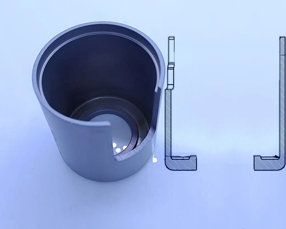
When a drawing calls out a finished wall on a drawn section, that wall is not the blank thickness. The blank starts thicker, and the wall thins as material bends over the die radius and is pulled down into the wall. Two different numbers are used in practice for how much survives: a drawing may be built on the assumption that the wall finishes at about 85 percent of blank thickness, while a process analysis for that geometry, grade and reduction sequence indicates that roughly 75 percent is achievable.
The arithmetic is where the gap appears. On a 1.0 mm blank the difference is 0.85 mm against 0.75 mm. If the wall callout is 0.75 mm plus or minus 0.05 mm, an 85 percent assumption implies a blank of about 0.88 mm and predicts a wall of roughly 0.75 mm. At the achievable 75 percent, the same blank produces a wall of about 0.66 mm, outside the low limit before die wear has contributed anything. The correction is one of three: start from a 1.0 mm blank and re-examine the finished wall, add an ironing operation to bring the wall back to size, or widen the wall band.
This is a quotation-stage calculation, not a production discovery, and that is the useful part. A thinning figure that is never tested against the specific reduction sequence, corner radius and grade is an assumption rather than a result, and it is cheapest to test while the blank thickness is still open. Where the finished wall must be held tightly, an ironing pass closes part of the gap at the cost of one more station; the clearances and surface consequences are set out under ironing in deep drawn stamping.
Worked example: how the operations fall out of the geometry
Take a flanged cylindrical cup in DC04, 1.0 mm thick, 45 mm outside diameter, finished height 60 mm, with a 3 mm trim allowance on the drawn height. Developed height 63 mm, blank diameter about 116 mm, total draw ratio 2.58. Applying the mild-steel windows from the table above, and putting the trim allowance on the drawing rather than in a note, as the engineering drawing guide explains, gives this sequence.
| Operation | Diameter after (mm) | Reduction in this step | Cumulative blank ratio | Note |
|---|---|---|---|---|
| Blank | 116 | - | 1.00 | Blanked from strip; developed height includes the 3 mm trim allowance |
| First draw | 72 | 37.9% | 1.61 | Largest reduction of the sequence; establishes the head radius |
| Second draw | 56 | 22.2% | 1.29 | Inside the redraw band for DC04 |
| Third draw | 45 | 19.6% | 1.24 | Finishes the diameter and the wall profile |
| Trim end | 45 | - | - | Removes the allowance and sets the finished height |
Three drawing operations, plus a trim. The first takes 37.9 percent, just below the 40 to 45 percent band for mild steel; the redraws take 22.2 and 19.6 percent, both within the 15 to 25 percent band. The plan does not sit hard against every limit, which is deliberate. A sequence that uses the full allowance on every step leaves no room for a thicker coil, a radius change or a grade substitution later, and those arrive on most projects.
Now reduce the finished height to 30 mm, developed 33 mm, blank about 90 mm. The same cup needs two operations: 90 to 54 mm at 40 percent, then 54 to 45 mm at 16.7 percent. Both steps sit inside the mild-steel windows, so two operations work, but each takes a larger bite than in the three-step plan and there is one less station in which a radius or a wall can be corrected. Both outcomes come from one equation: the step count follows the total reduction ratio and the way diameter changes are distributed along the part, not the height on its own.
When the answer is to change the part, not the process
Adding an operation is the process answer. It is not always the right one, because a station adds tooling, a press stroke per part, one more operation in which the wall can thin, and one more place for the die to wear. Before that step is added, the design-side levers are worth costing alongside it.
| Lever | What it actually changes | When it is the right answer | What it costs |
|---|---|---|---|
| Reduce the finished height | Developed blank diameter falls, so the total draw ratio falls and may drop a whole operation | The height is generous rather than functional | A drawing revision and nothing else in the tool, if the change is made before the die is cut |
| Increase the corner or head radius | Lowers local strain where the wall turns | The radius is cosmetic, or the mating part tolerates more | A drawing revision before tooling, or an insert afterwards |
| Accept a thicker blank or a wider wall band | Raises the amount of material that survives thinning | The wall dimension is not functionally critical | Material mass per part, and a wider inspection band agreed with the customer |
| Add a draw operation | Spreads the same total reduction over more steps | The geometry is genuinely required as drawn and the volume can carry the cycle time | One die station, one press stroke per part, and one more thinning risk |
| Add an interstage anneal | Restores ductility so the following step can take a larger reduction | The grade is austenitic stainless and the sequence is already long | Distortion to compensate for, cleaning, handling, and a furnace queue measured in days |
| Split the part into two drawn pieces | Takes the deepest reduction out of any single shell | The part is long relative to its diameter and a joint is acceptable | A joint, its tooling, its inspection and its strength or leak requirement |
| Move a feature to a machined face | Takes a detail off a formed wall that moves as the die wears | The feature tolerance is tighter than the wall tolerance it sits on | A machining operation, a second setup and a longer routing |
The rule of thumb: if the function does not need the height, the corner radius or the wall band that is causing the extra operation, changing the part is normally cheaper than changing the process. If it does need them, the extra operation is the honest cost of the geometry, and it belongs in the quotation as a stated operation count rather than as a discovery at first-off.
Interstage annealing is not a free substitute for an operation
An interstage anneal restores ductility that earlier draws consumed. Placed between two redraws it softens the work-hardened wall, which lets the following step take a larger reduction than it could otherwise carry. On multi-step draws in austenitic stainless that can be the difference between a plan that works in the requested number of operations and one that does not, and the furnace cycle itself is a controlled process rather than a bench operation.
It carries its own cost, and the cost is not small. Annealing relaxes residual stresses, so the part distorts: ovality and height both move, and the die has to be sized to compensate rather than to the finished print. Parts may need cleaning afterwards if the furnace atmosphere leaves scale, which adds handling on thin walls and a risk of marking. A furnace queue measured in days is a normal planning assumption, so an anneal inserted late moves the delivery date, not just the process. Planned from the start it is a reliable tool; added at first-off it is a schedule risk. The measurements that make it predictable are set out under heat treatment.
The boundary we state at quotation
Some parts cannot be drawn in the requested number of operations at the requested height, thickness and corner radius. The useful answer is to say so with the reason attached, rather than quote a tool that will not hold the geometry. When that happens we put the requested operation count next to the achievable one, name the specific cause - total reduction ratio, a corner radius below the practical floor, a wall that cannot survive the thinning, or a feature that cannot be formed on a drawn wall - and set out the options: one more operation, an anneal, or a change to the height, the radius or the wall band.
A clear refusal with a reason and a set of alternatives is worth more to a project schedule than a quotation that survives until first-off. If the geometry is essentially a machined part, or the reduction ratio sits outside what any practical sequence can reach, the same message applies: the process is wrong, not the die. Some of these limits are described in more detail in our note on capability boundaries. The figures in this article are the working windows we quote against, not absolute physical limits, and a trial on the actual blank is what settles a marginal case.
- Which dimension is functional: the height, the wall or the corner radius.
- The acceptable blank thickness band, given the wall thinning the sequence will produce.
- Whether an interstage anneal can be written into the routing and planned for.
- Whether the operation count in the quotation is the requested one or the achievable one.
- Which features must stay on the drawn wall and which can move to a machined face.
Before the operation count is fixed: Send the drawing with tolerances marked, the 3D model, the grade and the acceptable thickness band, the annual volume, and a note on which of the height, the wall and the corner radius is functional. With those five, the step count can be calculated and defended at quotation. Without the thickness band in particular, the arithmetic above can only produce a range.
Related reading on deep drawn stamping
These companion notes go deeper on the same engineering decisions:
- The Deep Drawing DFM Checklist Before Cutting Steel
- Deep Drawn vs Welded Housing: Is It Actually Sealed?
- Deep Drawn Housing Wall Thickness Tolerance: ID, OD and Wall
- Deep Drawn Stainless Steel Cracking: A Root-Cause Ladder
FAQ: FAQ: Draw steps, height and the thickness trade in deep drawing
Q: How many draw steps does my deep drawn part need?
A: It is calculated, not chosen. Divide the developed blank diameter by the finished diameter to get the total draw ratio, then subtract reduction step by step using the first-draw window for the grade and the narrower redraw window for each later operation. A 116 mm blank drawn to 45 mm in DC04 takes three operations; a 90 mm blank to the same 45 mm takes two. The number of operations is the output of that calculation, and the height is only one of its inputs.
Q: Why would a shorter part need more draw operations?
A: Because step count follows the distribution of diameter changes along the part, not the height. Reducing overall height compresses the distance between two changes in diameter or two stepped features, so one operation that previously served a single feature zone now has to establish two and takes a larger reduction in a single hit. The part is shorter but the reduction per step is higher, and that is what forces an extra operation.
Q: What is the maximum reduction in the first draw?
A: For mild steel such as DC01 or DC04, roughly 40 to 45 percent of blank diameter, falling to 15 to 25 percent on subsequent redraws. Austenitic stainless such as SUS304 or 316L is lower, commonly 30 to 38 percent on the first draw and 12 to 20 percent after it, because it work-hardens steeply. Aluminium, copper and brass each sit on their own scale. These are working windows that move with thickness, radius, clearance and lubrication, so treat them as a starting point for a trial rather than a guaranteed limit.
Q: Does a merged draw fail the same way as an overloaded draw?
A: No, and the difference matters. A draw that has exhausted material ductility fractures at a specific station. A merged draw that has exhausted the forming limit in a geometric sense produces an oversized head radius, a wrinkled flange or a die that will not hold size, without cracking. If the radius will not come in, restoring the separate redraw is the fix; more lubricant or a more formable grade will not change it.
Q: How much wall thinning should I allow for?
A: Assumptions of about 85 percent of blank thickness are common on drawings, while the achievable figure for a given geometry, grade and reduction sequence is often nearer 75 percent. On a 1.0 mm blank that is 0.85 mm against 0.75 mm, which decides whether the blank has to start thicker. Test the figure against the actual reduction sequence at quotation, because the same gap found after tooling becomes a new blank specification and new die clearances. Where the finished wall is tight, ironing closes part of the gap at the cost of a station.
Q: Is interstage annealing cheaper than adding a draw station?
A: Not automatically. An anneal restores ductility so the next redraw can take a larger reduction, but it relaxes residual stress and distorts the part, so ovality and height move and the die must be sized to compensate. It may also require cleaning if the atmosphere leaves scale, adds handling on thin walls, and occupies a furnace queue measured in days. Planned into the routing from the start it is reliable; inserted at first-off it becomes a schedule risk as well as a process change.
Q: What happens if my part cannot be drawn in the number of steps I have allowed?
A: We state the requested operation count next to the achievable one and name the cause: total reduction ratio, a corner radius below the practical floor, a wall that cannot survive the thinning, or a feature that cannot be formed on a drawn wall. The options are usually one more operation, an interstage anneal, or a design change such as reduced height, a larger radius or a wider wall band. All of them are cheaper to decide before die steel is cut than after.