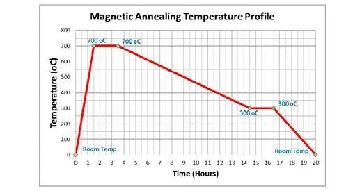
Summary
Interstage annealing does two things at once: it restores ductility for the next draw, and it releases the residual stress that the previous draws left in the wall. The second effect moves dimensions. Measured on thin-wall drawn shells, the tail inner diameter changes by 0.08-0.09 mm when the shell is unnotched and by 0.30-0.40 mm when a notch is already cut. Because the magnitude is set by the part's features rather than by the material alone, the safe route is to measure the distortion on a cold-formed sample from the real process, offset the die by that amount, and verify on the first article after annealing.
Most engineering drawings treat interstage annealing as a softness requirement. The material has work-hardened through several draws, the next reduction would crack it, so the part goes into a furnace and comes back ductile. That description is incomplete. The same thermal cycle that restores ductility also releases the residual stress the drawing operation left in the wall, and releasing stress means the part changes shape. On a thin-wall shell the movement is modest but rarely negligible; where the shell carries notches, windows or piercings, it can consume the whole tolerance band on its own. The practical conclusion is that interstage annealing deserves the same dimensional treatment as springback: measure it, then compensate the tool for it.
The effect is easier to accept once it is measured. Take four shells from one drawing process, nominally identical, and measure the tail inner diameter before and after the annealing cycle. Two of them, unnotched, moved 0.08-0.09 mm. The other two, notched, moved 0.30-0.40 mm. Same material, same furnace load, same nominal size, and a factor of three to four driven entirely by a geometric feature. That gap is why a single distortion allowance for a material grade is not useful: the number belongs to the part.
Why a notch multiplies the distortion
A deep drawn shell leaves the press with a residual stress field that is broadly axisymmetric: hoop compression toward the outside of the wall, tensile stress where the wall was thinned, and bending stress left around the die and punch radii. In an unnotched shell those stresses are close to equilibrium around the full circumference, so when the material yields during heating the shell relaxes more or less evenly. The diameter changes and the part stays round. The failure modes caused by the same stress field during forming are catalogued under metal working defects.
A notch breaks that symmetry. It removes a segment of the load path, so hoop stress has to flow around the opening, and it concentrates stress at the notch root. If the notch was sheared or pierced before annealing, it adds a stress field of its own, with a sign and direction unrelated to the draw. When the temperature rises and yield strength collapses, the material creeps toward a new equilibrium, and because stiffness around the circumference is no longer uniform it relaxes asymmetrically. Part of the 0.30-0.40 mm is movement at the notch itself; part is the shell distorting because one side is now more compliant than the other.
That leads to the single most useful rule in the topic: anneal before notching wherever the sequence allows. If the notch is cut after the anneal, the shell relaxes as an axisymmetric body, in the 0.08-0.09 mm class, and the notch is then cut into already-relaxed material in a station that has its own position control. The 0.30-0.40 mm class of distortion largely disappears, because the feature that causes it does not exist at the moment the thermal cycle runs. The trade-off is real but usually minor: the notch station then trims a softer, more ductile material, which shifts burr height, tool wear and the tonnage required.
The measured contrast, and the compensation it forces
The table below is the core of the specification. It is worth reading as a decision rule rather than as data: the condition of the part at the moment it enters the furnace determines both the expected movement and the die correction that follows from it.
| Condition at the furnace | Samples measured | Tail inner diameter change | Dominant mechanism | Die compensation action |
|---|---|---|---|---|
| Thin wall, unnotched | 2 | 0.08-0.09 mm | Near-axisymmetric relaxation of the draw residual stress field | Offset the final sizing station by the measured mean change, then verify on the first article |
| Thin wall, notched before annealing | 2 | 0.30-0.40 mm | Stress concentration and asymmetric redistribution around the notch | Move the notch after annealing if the sequence allows; otherwise offset both the notch position and the sizing station |
| Notched after annealing, preferred sequence | Confirm with a fresh trial | The unnotched class is what remains | The thermal cycle runs on an axisymmetric shell; the notch is cut into relaxed material | Compensate the sizing station only, and keep the notch station dimensionally independent |
Compensation is cycle-specific: A die offset is only valid for the annealing cycle it was measured on. Change the furnace, the atmosphere, the soak temperature or the cooling rate, and the offset has to be re-measured. Record the cycle on the tool history card next to the offset.
Pre-compensating the die: measure, offset, verify
Compensation is a short loop, but every step has to be done in the right order. Skipping the trial and estimating the offset from a handbook value is how a tool ends up in the correction loop for weeks. The steps below are the ones that matter for a drawn shell; the tooling decisions behind them are discussed in stamping die design.
- Draw the trial batch on the real process: same blank, same number of draws, same draw ratios, same lubricant, same wall thinning at the same stations that production will use.
- Anneal every trial sample in the same furnace load, on the exact cycle that production will run, including the atmosphere and the cooling rate.
- Measure the features the drawing actually tolerances, before and after the anneal: tail inner diameter, roundness, overall length, notch position, and wall thickness at the measuring points.
- Convert the change into a die offset. For an inner diameter that grew, reduce the sizing punch or increase the sizing die by the measured mean; if wall thickness must be held, split the offset between punch and die.
- Cut the compensation into the tool, run a first article through the complete sequence including the anneal, and re-measure. First-article documentation follows the same route as any other dimensional report under quality and certifications.
- Record the measured offset and the cycle on the tool history card, so the next tool for the same part family starts from a known number instead of from scratch.
Treat the offset as provisional until production proves it. Furnace loads vary in thermal mass, parts sit at different positions in the load, and a slightly different soak time moves the result. The offset removes most of the error; the first article confirms the rest.
Make the prediction sample by cold forming, not by turning
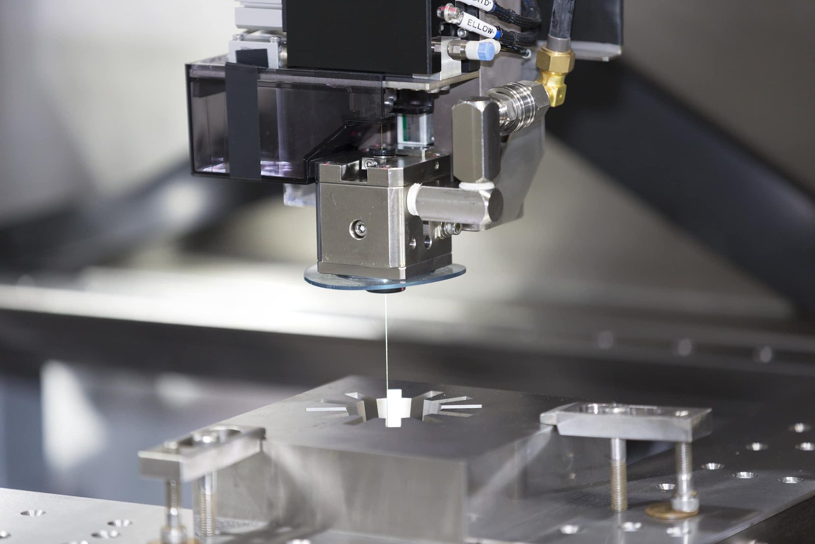
There is a subtle trap in sampling for this measurement, and it is worth stating plainly: the sample used to predict annealing distortion should be made by cold forming, not by CNC turning. It sounds pedantic until you consider what is being measured. The quantity of interest is not the geometry, it is the residual stress field, and a turned sample has essentially none. The bar was stress-relieved before turning, the cutting forces are small and local, and the finished part is dimensionally exact but metallurgically a different object. Anneal it and it will barely move. Put that number into a die compensation and the real drawn part lands a couple of tenths of a millimetre away from the prediction.
The prediction sample must carry the deformation history of the intended process: the same number of draws, the same draw ratios, the same blank thickness, the same lubricant, the same wall thinning at the same stations. If the trial runs on a short-run die with three draws while production will use four, the residual stress field differs and the compensation is wrong. This is a real cost inside a compressed sampling programme, and it is one of the boundaries we are honest about in our deep draw capability boundaries: a fast trial on a simplified tool buys schedule, but it does not buy a valid distortion number. Four samples are enough to reveal the notched versus unnotched split; ten per condition is a better basis for a production offset.
Vacuum or air: bright part, black part, and what it costs
Atmosphere is the parameter that decides what the part looks like when it comes out, and it is usually decided early because it determines which furnace the job goes on. Vacuum annealing leaves the surface bright. Annealing without vacuum oxidises the surface and turns it black, and the scale thickness grows with temperature and time at temperature. That difference is not cosmetic if the part will be plated, assembled into a visible location, or left as-drawn; the follow-on operations are covered under surface treatment.
| Atmosphere | Surface after annealing | Relative cost | Use it when |
|---|---|---|---|
| Vacuum | Bright, no oxide scale | Highest of the three; vacuum loads are usually booked in larger batches | The part is visible, will be plated, or will not be pickled or machined afterwards |
| Controlled protective atmosphere | Bright to light grey if the dew point is held | Moderate | Stainless parts that need a clean surface but are not colour-critical |
| Air, no atmosphere control | Black oxidised surface; scale grows with temperature and time | Lowest | Parts that will be pickled, blasted or machined after annealing |
A bright finish matters most where nothing downstream will remove a damaged layer: a plated housing needs a clean substrate or adhesion suffers, a visible trim surface cannot be recovered once it is scaled, and a part that goes straight to assembly has no second chance. Where a pickling or blasting step already exists in the route, air annealing is defensible and cheaper. Between the two extremes sits lower-temperature semi-finished annealing, which has been used to cure a rough surface and internal blackening. Whether functional properties after that treatment are identical to a full anneal is a fair question and one we would rather answer with test data on the specific part than with a general claim.
Parameters to agree before the furnace is booked
A specification that says only a temperature is not a specification. Where a drawing or an enquiry names a single set point, the productive reply is a table of the whole cycle, with each line tied to the property it protects. This is the list we would want agreed in writing before a trial load is scheduled.
| Parameter | What to specify | What it protects |
|---|---|---|
| Temperature and soak | One set point plus a minimum soak at temperature, with the thermocouple position defined | Ductility for the next reduction, without grain growth and unnecessary scale |
| Atmosphere | Vacuum, a controlled protective atmosphere, or air | Surface colour, scale thickness, and the hardness response of any later hardening step |
| Heating rate | Rate up to the soak, or a maximum permitted furnace ramp | Wall-thickness thermal gradient, which is what warps a thin shell before it ever reaches the soak |
| Cooling rate | Furnace cooling, controlled cooling, or a maximum rate down to a defined unload temperature | Final hardness and ductility, and re-introduction of thermal stress on the way down |
| Cleanliness before annealing | Degreased, no drawing lubricant, no fingerprints, dry | Carbonised residue and stain marks that no later operation will remove |
| Cleanliness after annealing | Handling method, packaging, and whether pickling or blasting is allowed | Surface finish before plating or assembly, and contamination of the next furnace load |
| Load arrangement and records | Batch size, part orientation, and the temperature record issued with the parts | Repeatability between the trial load and the production loads |
Scale, and the hardening step it can ruin
Oxide scale is not only a surface appearance problem. On a part that will be hardened after annealing, thick scale carries the risk that hardness will not come up to specification, and the risk compounds on parts that are annealed repeatedly. The surface layer that scale and its underlying depleted zone represent is precisely the region a hardness test or a wear surface depends on, and a part whose hardness misses the specification after quenching is generally scrapped rather than reworked.
The consequences for process planning are straightforward. If a drawn component will be through-hardened or case-hardened later, the interstage anneal should run under vacuum or a controlled atmosphere, and any scale that does form must be removed before the hardening step rather than after. Repeated annealing should be avoided where the sequence permits it: two anneals mean two chances to build a scale layer and two chances to grow the grain. For stainless grades, where the surface chemistry matters as much as the geometry, the same logic applies with less margin. Material selection and its heat treatment response are discussed under stainless steel for deep drawn parts.
Demagnetisation: verify it, do not assume it

An annealing cycle that takes the material above its Curie temperature and cools it without re-imposing a field also demagnetises it. This is mainly relevant for stainless, and for magnetic-circuit parts it is not a side benefit but a functional requirement. A drawn housing that forms part of the magnetic circuit of a solenoid or valve behaves differently if it retains a magnetic field: pull-in and release characteristics shift, successive actuations may not repeat, and the part can hold ferrous wear particles inside a bore where they eventually cause a failure. These are the parts we produce as deep drawn solenoid valve housings, and the acceptance criterion has to be written down rather than assumed.
The honest position is that not every shop can verify it. It is common for a supplier to have no residual-magnetism measurement in place at all, particularly for cold-rolled low-carbon sheet where the topic never comes up, and to ask the buyer for reference values for temperature, time and cooling instead. That is a reasonable request, and the useful answer is a measured value at defined points rather than a promise. Specify the maximum residual flux density, the instrument, the distance and the points at which it is checked, and the number of parts sampled. A cycle that demagnetises in one furnace load may not do so in the next if the arrangement or the cooling rate changes, so the check belongs on the dimensional report as a recorded result.
Sequencing, queue time, and what is genuinely unsettled
Furnace time is a scheduling constraint as much as a process one. Outsourced annealing depends on a queue, and a queue can push a sample schedule out by around ten days on its own, which changes the tooling plan far more than it changes the part. One response is to bring the furnace in-house: it removes transport between operations, keeps the cycle under direct control, and makes a trial anneal possible on the day it is needed rather than the week it is needed. The alternative is to accept the queue and build the tool plan around it, running non-annealing work in parallel. Either choice is defensible; what is not defensible is discovering the delay after the first-article date has been promised.
One question in this area remains open in our own practice: whether to anneal before or after the last draw is not settled. Annealing before the last draw leaves the final draw strain in the part, which helps strength but leaves the dimensions less stable across subsequent operations. Annealing after the last draw produces the most stress-free and dimensionally stable part, but it hands a soft, easily damaged component to the rest of the sequence, and any sizing after that reintroduces stress. The right answer depends on the draw ratio, the hardness requirement and how much handling the part will see, so it should be decided per part and recorded in the process control plan with the reasoning attached rather than left to the shop floor.
Before a trial load is booked, the following information is worth fixing in writing, because each item changes the result:
- The temperature, soak time, heating rate and cooling rate that will be used in production, not only in the trial.
- Whether the notch or piercing is cut before or after the anneal, and which station performs it.
- Whether vacuum or a protective atmosphere is required, and what surface condition is acceptable after unloading.
- Whether demagnetisation is a requirement, and if so the maximum residual flux density and how it is checked.
- Whether any hardening step follows the anneal, since that decides how much scale is tolerable.
- The order of operations around the furnace, so that transport and queue time appear in the tool plan instead of the schedule.
Related reading on deep drawn stamping
These companion notes go deeper on the same engineering decisions:
- Deep Drawn vs Welded Housing: Is It Actually Sealed?
- Inspecting Deep Drawn Parts: Radius, Runout, Concentricity
- DC01 vs DC04 vs SPHC vs SPHE: Which Grade?
- How Many Draw Steps Does a Part Need?
FAQ: FAQ: Interstage annealing and dimensional distortion
Q: How much does interstage annealing actually move a deep drawn part?
A: On the thin-wall shells we measured, the tail inner diameter changed by 0.08-0.09 mm on unnotched samples and by 0.30-0.40 mm on samples that were notched before annealing. The difference is driven by the notch, not by the material grade. Treat any figure as specific to the part and the cycle, and measure it on samples from the real drawing process.
Q: Should the notch be cut before or after annealing?
A: After, wherever the sequence allows. If the shell is axisymmetric when it enters the furnace it relaxes evenly and the distortion stays in the 0.08-0.09 mm class. If the notch already exists, the hoop stress redistributes asymmetrically and the movement grows to roughly three or four times as much. The cost of moving the notch later is a softer material at the trimming station, which affects burr height and tool wear.
Q: Can a CNC-turned sample be used to predict annealing distortion?
A: No. A turned sample has the geometry but not the residual stress field left by drawing, so it barely moves when annealed. The prediction sample has to be cold formed on the same sequence, with the same number of draws, draw ratios and wall thinning, because residual stress representativeness is the entire measurement.
Q: Why do we need vacuum annealing rather than air annealing?
A: Because the atmosphere decides the surface. Vacuum leaves the part bright and free of scale; air annealing oxidises the surface and turns it black, and the scale grows with temperature and time. Vacuum costs more and is usually booked in larger batches, so it is worth it where the part is visible, will be plated, or will not be pickled or machined afterwards.
Q: Does annealing demagnetise a stainless drawn housing?
A: Yes, if the cycle takes the material above its Curie temperature and cools it without re-imposing a field. For solenoid and valve housings that is a functional requirement, because residual magnetism shifts pull-in and release behaviour and can hold ferrous particles in a bore. It should be verified with a measurement at defined points, not assumed from the fact that an anneal took place.
Q: Why did hardness not come up after quenching?
A: Thick oxide scale from a previous anneal is a common cause, especially on parts that have been annealed more than once. The scale and the depleted layer beneath it are exactly the region the hardness depends on. Anneal under vacuum or a protective atmosphere if a hardening step follows, and remove any scale before quenching rather than after.
Q: How much time does annealing add to a sample schedule?
A: A furnace queue alone has pushed a sample schedule out by around ten days, which is usually longer than the tooling work it is waiting on. Options are to plan the tool build around the queue and run non-annealing operations in parallel, or to bring the furnace in-house so the trial anneal happens when it is needed and transport between operations disappears.