
Summary
A deep drawn housing is one continuous piece of metal, so the pressure boundary has no joint and no seam to leak. A coiled or welded housing has a longitudinal seam and is therefore not 100 percent sealed by construction, which is a structural verdict rather than a workmanship complaint. The real trade-off is material against process, and on some projects the welded or custom cold-drawn tube is genuinely the tighter choice.
The short answer: one piece versus a seam
A deep drawn housing is formed from a flat blank into one continuous piece of metal, so the pressure boundary contains no joint and nothing to leak. A coiled or welded housing is strip rolled into a cylinder and closed along a longitudinal seam. That seam is a physical discontinuity, and even a sound weld is a different metallurgical path from the parent metal. The welded version is therefore not 100 percent sealed by construction, rather than leaking at some particular pressure.
What follows is not sealedness against everything else. It is material against process. A coiled housing uses less raw material, because strip is cut to the developed circumference instead of a blank large enough to feed a drawn wall, but it uses more operations: forming, seam closing, welding, dressing, sizing, inspection. A drawn housing inverts that, with more material and fewer operations. Across a real project the two totals often land close together.
| Criterion | Deep drawn | Coiled / welded | Seamless tube | Custom cold-drawn tube |
|---|---|---|---|---|
| Sealedness | One piece, no joint | Seam; not 100 percent sealed | No seam, but end joints and eccentric wall | Seam can sit on the OD and be turned away |
| Dimensional capability | Set by punch and die; best on medium lengths | Tighter than usually assumed, from pre-rolled strip | Not automatically precise; pierced wall varies | Highest: sub-0.01 mm bore and OD bands |
| Material efficiency | Lower; blank feeds wall, bottom and trim | Higher; strip cut to developed length | High; bought as stock tube | High, but turning removes material |
| Process count | Few; draw sequence in one or two tools | Many; form, weld, dress, size, test | Fewest at part level, separate supply chain | Few; drawing and turning at the supplier |
| Wall uniformity | Die clearance and the ironing pass | Inherited from strip thickness tolerance | Eccentricity across the wall | Set by mandrel and die, very uniform |
| Internal surface | No weld scar; tool marks are the risk | Weld bead or scar inside unless dressed | Smooth bore | No scar when the OD is turned |
| Where it wins | Absolute sealing, closed end, high volume | Long parts, mid tolerance, weld capability | Standard sizes, commodity chain | Sub-0.01 mm bore, long slender part |
What a seam does to a leak path
In the welded design the seam itself is the path. Because it runs the full length of the housing, the distance a gas must travel to escape is only the wall thickness. Welded joints fail in specific ways: porosity, undercut or lack of penetration leave a channel; the heat-affected zone has a different grain structure and can crack in service; a locked seam relies on interference, which is sensitive to strip springback and burr height, so a coil change can open a micro-gap.
- Incomplete penetration or porosity along the seam
- Undercut at the weld toe, a notch in the wall
- Heat-affected-zone cracking after sizing or necking
- Micro-gap in a locked seam after springback
- Internal weld scar, also a particle risk
What buyers actually write: A common requirement is not a leak rate at all: no visible weld seams or weld scars inside. Surface quality is used as a proxy for sealing integrity, and reasonably so, because a seam dressed from outside can still leave a scar where the seal seats.
The material-versus-process offset in relative numbers
The routes compare more cleanly as ratios than as absolute figures. Take a thin-wall housing of roughly 40 mm diameter, 35 mm depth and 1.0 mm wall. A drawn blank must carry the wall, the bottom and the trim allowance, so blank area typically lands at 1.6 to 2.2 times the finished wall area, and most of that difference leaves the press as skeleton and trim scrap. The rolled route buys strip close to the developed circumference plus a seam allowance, so purchased mass per part can be well under half of the drawn blank mass.
That advantage is then spent in operations. A drawn housing of this shape needs roughly four to six forming and trimming operations inside one or two tools, with a single setup. A welded housing needs the strip roll-formed, the seam closed and welded, the weld dressed, the diameter calibrated, the ends finished and the part leak-tested. Each step adds handling, a fixture and a yield loss. Saving around half the material mass is often cancelled by two or three extra operations and their scrap; the two routes usually finish close on total delivered cost.
The offset also shifts with shape. The deeper and narrower the part, the more of the blank is trimmed away; the longer and thinner it is, the more the tube route gains, because a drawn punch loses bore control over depth. This is where the choice stops being commercial and becomes geometric; both families are described under deep draw metal stamping capability.
The assumption that fails: seamless is not automatically precision
The usual assumption is a ladder: seamless tube better than welded tube, both better than drawing. The first step does not survive contact with tolerance. On one project carrying a ±0.1 mm bore requirement, the tube mill replied that it could not hold that band and that the best it could do was ±0.2 mm, while the welded alternative was reported as dimensionally tighter on the same feature. The requirement then escalated to a custom cold-drawn tube at ID 2.71 ±0.003 mm against OD 2.933 ±0.003 mm.
The mechanism is not mysterious. A welded tube is made from cold-rolled strip whose thickness tolerance was fixed at the rolling mill, then formed and welded, so wall variation around the circumference is largely inherited from controlled strip. A seamless tube is pierced and worked from solid, and without a weld to close the geometry the wall tends to vary around the circumference while the bore centreline can sit off the OD centreline. Grip the housing on its OD and run a spool in the bore, and that eccentricity appears as a functional error.
Tolerance in that band must also be policed, not merely certified. Sampling a delivered lot against a dimensional report is normal, and a lot failing is not unusual: one rejection covered 8 of about 22 checked dimensions on a single delivery. That argues for incoming inspection with real measured data, in the terms described under quality and certifications, rather than a certificate alone.
When welded or cold-drawn tube is genuinely better
Sealedness is not the only requirement on a housing. Where a seam is irrelevant, the tube route wins clearly, and the decision guide below separates the two cases on function rather than on habit.
| Requirement on the part | Route to choose | Why |
|---|---|---|
| Absolute sealing; the part is a pressure or vacuum boundary | Deep drawn | No seam anywhere in the pressure boundary |
| No internal weld scar permitted, or the inside cannot be reached for dressing | Deep drawn | The internal surface is formed, not welded, and needs no dressing |
| Closed end, step, flange or seat blended into the bore | Deep drawn | The geometry comes out of the draw sequence as one piece |
| High annual volume | Deep drawn | A progressive or transfer tool is amortised over a long run |
| Sub-0.01 mm bore tolerance on a long slender part | Custom cold-drawn tube | Drawn over a mandrel along its whole length, so tolerance holds over depth |
| A weld scar that must still be removed from the seal band | Custom cold-drawn tube, OD turned | Turning relocates the seam off the sealing surface |
| Very low annual volume | Tube cut to length | Avoids a draw tool that may never be amortised |
| An existing standard tube size already in the supply chain | Welded or seamless tube | Keeps incoming inspection and stocking unchanged |
| A plain sleeve with no airtightness requirement | Welded tube | The seam is cosmetic and can sit outside any sealing band |
A deep drawn housing is normally right when the requirement is absolute, when the internal surface cannot be reached for dressing, when the geometry needs a closed end, a step or a seat blended into the bore, or when volume is high enough to amortise a progressive or transfer tool.
Choosing drawing for the wrong reason is just as common: it is not automatically tighter, nor automatically cheaper. On a thin-wall part with a demanding bore, a welded or cold-drawn tube can be both.
The seal is the absence of tool marks, not a gasket
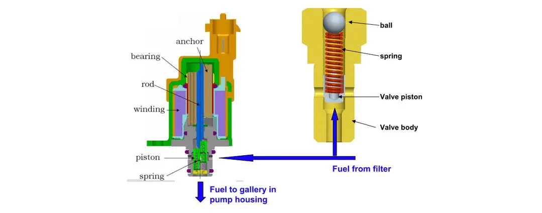
In a thin-wall drawn housing that holds a steel ball or a poppet, nothing is added to create the seal. The position holding the ball is a closed region with an airtightness requirement, and metal-to-metal contact between ball and seat is the seal. The acceptance criterion for that surface is optical rather than dimensional: as long as no drawing line is visible at 10× magnification, the part will pass the leak test. A line crossing the sealing band is a channel from inside to outside, and marks running along the direction of material flow are the ones to look for, because they cross the contact band instead of running around it.
That criterion is only usable if it is defined well enough to measure. Magnification and lighting both matter, and so does viewing angle, because a mark invisible under diffuse light can be obvious under a low-angle beam. Where a dispute is possible, a boundary sample is the cheapest instrument available: one part that just passes and one that just fails, photographed at the agreed magnification and kept with the drawing, as set out in our engineering drawing guide.
A drawing note that works in practice: Seat surface, closed region, airtightness required. No drawing lines or tool marks visible at 10× magnification under diffuse illumination at about 500 lux, viewed normal to the seat. 100 percent leak test with dry air at 0.4 to 0.6 MPa, 10 s hold, no bubble release under water. Boundary samples approved at first article.
Specifying the internal surface where a seal seats
Surface finish at a seat is not decoration; it is the sealing mechanism, so it belongs on the drawing with the same status as a diameter. Two specifications work together: a maximum Ra across the seal band, and the visual criterion above. Ra alone will not catch a single deep circumferential scratch, and the visual criterion alone will not catch a uniformly rough surface that weeps. Where geometry allows, the seal band should sit on an ironed section of the wall, because ironing reduces wall thickness under controlled clearance and improves dimensional control and finish together — the same tooling decision that holds the bore also produces the surface, as covered in ironing tolerances and surface finish.
Specify the lay or direction of the finish as well as its value where turning or grinding produces it. On an as-drawn surface the finish requirement is really a die-polish requirement, and the drawing should say so: the supplier then knows that polishing the punch at the seat station is a controlled process step rather than a final clean-up.
| Sealing feature | Why it leaks when wrong | What to specify |
|---|---|---|
| Ball or poppet seat in a drawn bottom | A drawing line crossing the circular contact band forms a channel | Maximum Ra on the band, no visible drawing line at 10×, leak test, boundary samples |
| Radial seal land, O-ring or lip seal | Axial scratches and out-of-roundness stop the elastomer seating | Bore diameter and roundness, maximum Ra, no axial tool marks |
| Spool or piston bore | Wall eccentricity and taper cause blow-by | Bore tolerance over full length, straightness, eccentricity limit |
| Staked or riveted insert | The stake deforms metal and can leave a path past the insert OD | Stake position and depth, no through crack, leak test after assembly |
| Necked or flanged tube end | Necking thins the wall and can crack the transition radius | Neck diameter, transition radius, no cracks at 10×, leak test after forming |
| Welded or brazed joint | Porosity, undercut and heat-affected-zone cracking | Weld procedure, penetration, internal scar dressed, weld inspection and leak test |
Post-draw operations that can open a leak path
Most sealedness failures on drawn housings are not caused by the draw itself. Necking or flanging a tube end is a common cause: the operation reduces diameter in a transition zone, thins the wall locally and can crack it. A crack there may be a fraction of a millimetre long and invisible without magnification, yet it crosses the wall from inside to outside. Accepting a necked end therefore needs a magnification criterion as much as a dimensional one, and a leak test after forming rather than before, as catalogued under metal working defects.
Staking an insert is the second case, and it is routine in solenoid valve housings where a washer or disc must be locked into a drawn shell. A form-fit stake presses the wall radially into the insert with a small punch, and the working rule is that punch diameter should be smaller than wall thickness so the material cold-flows into the insert instead of punching through. Even then the sealing risk is not the stake mark but the annular gap between insert OD and housing ID: if displaced material does not fill that gap continuously around the circumference, the gap becomes a leak path. Where the location is a sealed region, require a leak test after assembly and apply the visual criterion to the insert interface, not only to the bore.
The order of joining and coating is a third, less obvious route to failure. Staking before plating leaves unplated crevices that corrode; plating before staking breaks the coating at the deformed zone, and the broken edge sits exactly on a crevice. Neither sequence is universally right, but the decision has to be deliberate and written into the process.
Running the selection as a five-step check
- Write the sealedness requirement in the form it will be tested: absolute with a leak test, a quantified leak rate, or no requirement at all.
- Identify the sealing features and their tolerances. The tightest of them drives the process choice.
- Estimate depth-to-diameter ratio and overall length. Above roughly 3:1 for a deep bore, expect drawn bore control to become the limiting factor.
- Compare the routes on function first, then on material mass and operation count. If they land within a few percent, the sealed design should normally win.
- Write acceptance as a visual criterion, a leak test and a boundary sample, and name the measuring equipment, so the requirement survives transfer to production.
Where our capability stops, and where a tube is the honest answer
We deep draw and progressive-die stamp housings in SUS304 and 316L, SPCC, DC01 and DC04, copper and brass, aluminium, SPTE and DT4E, on presses from 25 to 350 t, with in-house tool design and build. Drawn housings with closed ends, stepped bores, formed seats and staked inserts are core work, and the surface and leak criteria above are familiar acceptance requirements. We do not operate a tube mill, so when the analysis says a custom cold-drawn tube is correct, the useful response is to say so rather than force the part into a process we do not run.
The dividing line is the one this article describes: with a seal, a closed end or a formed seat, drawing is usually right; on a long slender bore at sub-0.01 mm, tube usually is. The wider limits of the drawn route, including the wall-thickness reductions and depth ratios that can be held reliably, are set out in our capability boundaries.
Related reading on deep drawn stamping
These companion notes go deeper on the same engineering decisions:
- How Many Draw Steps Does a Part Need?
- The Deep Drawing DFM Checklist Before Cutting Steel
- DC01 vs DC04 vs SPHC vs SPHE: Which Grade?
- Tightening a Tolerance: What It Costs in Tooling
FAQ: FAQ: deep drawn vs welded housing sealedness
Q: Is a deep drawn housing always leak-tight?
A: No. It has no seam, so the pressure boundary itself is continuous, but it can still leak at a ball seat, a staked insert, a cracked necked end or a porous weld added later. The draw removes the seam as a leak path; it does not remove the need for a leak test after all forming and assembly operations.
Q: Why is a coiled housing described as not 100 percent sealed instead of leaking at a stated pressure?
A: Because the seam is a continuous structural interface rather than a discrete defect. Whether it passes gas depends on surface finish, springback, seam interference, coating and temperature, so no single pressure figure describes it honestly. A one-piece drawn housing has no comparable interface, which is why the distinction is stated structurally.
Q: Can a welded tube really be more accurate than a seamless tube?
A: Yes, for some features. A welded tube inherits wall thickness tolerance from cold-rolled strip rolled to a known band, so circumferential variation is small. A pierced seamless tube has no weld to close the geometry and its wall tends to vary around the circumference. In one case a tube mill could not hold ±0.1 mm and offered ±0.2 mm while a welded tube was reported as tighter on the same feature.
Q: When should we specify a custom cold-drawn tube instead of a drawn housing?
A: When the tolerance is sub-0.01 mm on a long slender bore, when annual volume is too low to amortise a draw tool, or when the tube size already exists in the supply chain. One specification of this type ran ID 2.71 ±0.003 mm and OD 2.933 ±0.003 mm with the OD turned to remove the internal weld scar. Expect to police that band by sampling, because a delivered lot was rejected on 8 of about 22 checked dimensions.
Q: How do you write leak-tightness into a drawing when there is no gasket?
A: Combine three things: a visual criterion on the seal band, a leak test, and a boundary sample. The visual criterion should state magnification, illumination and viewing angle, for example no drawing line visible at 10× under diffuse illumination at about 500 lux. The leak test should state medium, pressure, hold time and pass condition, and it should run after every forming or assembly step that touches the seal region.
Q: Does a welded seam always have to be a problem?
A: No. If the housing is not a pressure or vacuum boundary, the seam does not matter. If the part is a plain sleeve, or the seam can be positioned outside the seal band or removed by turning the OD, the welded route stays viable and can be more accurate on bore-related features than a seamless tube.
Q: Which post-draw operations most often cause leaks?
A: Three stand out: necking or flanging a tube end, which thins and can crack the transition radius; radial staking of an insert, where the annular gap between insert and housing wall is not filled continuously; and the coating sequence, because staking after plating breaks the coating and plating after staking leaves unplated crevices. Leak testing after the operation, not before, is the only reliable control.