
Our Metal Fabrication Capabilities
Four manufacturing groups form a complete capability cluster — each links to its detailed page covering process route, materials, tolerances and quality control.
Metal Stamping
For sheet and strip parts, the stamping route — progressive die, deep drawing or precision stamping — is selected around geometry, material, precision and production volume.
View Metal Stamping Overview →Metal Machining
For rotational parts, block parts, precision interfaces and complex profiles — CNC turning, CNC milling and wire EDM routes.
View Machining Overview →Sheet Metal Processing
For brackets, panels, frames, enclosures and housings — cutting, bending, joining, surface treatment and assembly.
View Sheet Metal Overview →Tube Processing
Laser tube cutting, CNC tube bending and coiling for tubular parts, formed tubes and related assemblies.
View Tube Overview →Which Manufacturing Route Fits Your Part?
What Parts Can We Manufacture?
Part types below come from real applications and cases — each links to the corresponding application page.
Sensor Housings
Deep drawing / precision stamping · stainless, aluminum
Solenoid Valve Parts
Drawn housings / sleeves · steel, stainless
Magnetic Sleeves
Thin-wall drawing · stainless steel
Motor Housings
Drawn shells / end caps · steel, aluminum
Spring Cups
Drawn forming · steel, stainless
Washers
Precision stamping · multiple materials
Tube Assemblies
Cutting / bending / assembly · steel, copper
End Caps
Drawn forming · steel, stainless
What Materials Do We Support?
Material grade, temper, thickness and surface condition directly affect forming behavior and tool design, and are confirmed before tooling.
Stainless Steel
For stamping, deep drawing and precision forming; review material condition, work hardening, surface state and downstream treatment.
Carbon Steel
Brackets, washers, housings; strength, springback and corrosion protection evaluated with the process.
Aluminum
Weight and corrosion priorities; alloy and temper directly affect bending, drawing and springback.
Copper
Conductive and appearance parts; surface protection and handling built into the process plan.
Brass
Conductivity, appearance and formability; grain direction and surface treatment confirmed up front.
Special Alloys
Titanium and special alloys evaluated after a full material and geometry review.
Which Industries Do We Serve?
Main industries based on real project experience.
Automotive
Sensor housings, brackets, washers and solenoid valve parts requiring consistent assembly.
Solenoid / Valve
Drawn housings, sleeves, spring seats and magnetic or fluid-control components.
HVAC & Refrigeration
Tube assemblies, housings and structural parts where geometry and cleanliness matter.
Industrial Equipment
Brackets, guides, locking parts and assembly hardware made to specific drawings.
Material × Process Capability Matrix
The matrix below summarizes Balford's main manufacturing capabilities as an engineering reference for initial project orientation.
| Process | Aluminum | Brass | Cold-Rolled Steel | Hot-Rolled Steel | Stainless Steel | Galvanized Steel | Copper | Titanium |
|---|---|---|---|---|---|---|---|---|
| Punching | ✓ | ✓ | ✓ | ✓ | ✓ | ✓ | ✓ | Per project review |
| Bending / Sheet | 0.4–10 mm | 0.4–10 mm | 0.4–10 mm | 0.4–10 mm | 0.4–10 mm | 0.4–10 mm | 0.4–10 mm | Per project review |
| Bending / Tube | Tube OD up to approx. 65 mm (depends on material, wall thickness and bend radius) | |||||||
| Deep Drawing | Max diameter approx. 300 mm (depends on geometry, material and process route) | |||||||
| Coiling / Tube | Tube OD up to approx. 200 mm (depends on material and tube condition) | |||||||
| Tapping | ✓ | |||||||
| Deburring | ✓ | |||||||
| Centerless Grinding | ✓ | |||||||
| Polishing | ✓ | |||||||
| Annealing | ✓ | |||||||
| Surface Treatment | ✓ | |||||||
| Strip Brazing | ✓ | |||||||
| Riveting | ✓ | |||||||
| Machining | ✓ | |||||||
These capability ranges are for initial project orientation. Final manufacturability, dimensions, tolerances and process route are confirmed against the specific drawing, material condition, quantity and functional requirements. Specific parameters such as minimum punch diameter or forming tonnage are confirmed after drawing review.
Quality & Inspection
Quality control is not limited to final inspection. For OEM projects, material, process, critical dimensions, surface finish and assembly relationships are managed continuously from the early drawing review.
Material Verification
Material grade, thickness and condition verified against the approved production specification.
First-Piece / Initial Inspection
First-piece and in-process checks cover critical dimensions, appearance and material requirements.
In-Process Inspection
Tooling condition, feeding, setup and process stability monitored per the production plan.
Final Inspection & Documentation
Final checks per drawing; FAI, PPAP, IMDS, RoHS-related records and other customer documentation can be discussed when part of the project requirements.
One Project, One Coordinated Review
Many OEM parts are not completed by a single process. Stamped parts may need machining, surface treatment and assembly; sheet metal parts may need welding and coating; tube parts may need cutting and fixtures. Balford considers the datums, tolerances, surface finish and inspection requirements across these operations during the review phase — Balford does not push every part into one process, but selects the manufacturing route from the part drawing.
From Drawing to Production
The complete project flow, from drawing and requirements review through inspection and delivery.
Representative Manufacturing Case Studies
Real parts, real materials, real manufacturing requirements — each case links back to the corresponding capability, material and application pages.

ABS Wheel Speed Sensor Housing

Precision Stamped Stainless Steel Nut Washer

65Mn Spring Steel Shim
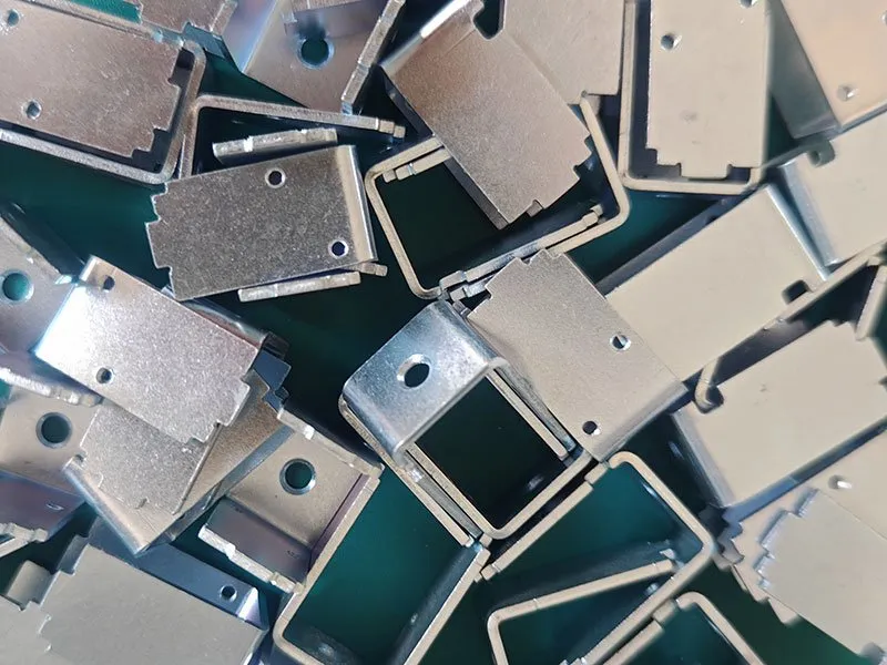
Solenoid Valve Housing
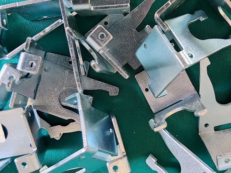
Stamped Metal Bracket

Thin-Wall Aluminum Tube
Project Response
Clear time commitments from quotation to sampling.
Quote Response
Typically within 24 hours of receiving complete drawings and requirements — or we confirm what information is still needed.
DFM Feedback
Initial DFM feedback typically within 48 hours of receiving complete information; timing depends on project complexity and completeness.
Sample Lead Time
Samples typically ship within 7–30 days depending on process, tooling and project requirements.
Metal Fabrication FAQ
Answers based on drawing review — material, geometry and production volume determine what is practical.
Balford's main capabilities include metal stamping, progressive die stamping, deep drawing, precision stamping, CNC turning, CNC milling, wire EDM, sheet cutting, metal bending, laser tube cutting, CNC tube bending, coiling and assembly/subassembly. The specific route is determined by the part drawing, material, quantity and functional requirements.
It depends mainly on part structure, material, precision, quantity and downstream operations. Stamping suits repeat sheet/strip parts; CNC suits rotational or block parts with complex local features; sheet metal suits sheet-structure parts.
Yes. Based on the 2D drawing, 3D model, material, quantity, critical dimensions and downstream requirements, Balford evaluates stamping, CNC, sheet metal, tube or combined routes and confirms the tooling, fixtures and inspection plan needed.
For suitable projects, stamping, machining, sheet metal, tube processing, surface treatment, heat treatment and assembly can be coordinated, with datums, tolerances and inspection requirements considered across the sequence during early review.
Main materials include stainless steel, carbon steel, aluminum, copper, brass and selected special alloys. Specific grades, material condition and thickness are confirmed against the part and process requirements.
Provide the latest 2D drawing, 3D model if available, material grade and condition, estimated purchase quantity, surface finish requirements, critical dimensions and assembly context. The more complete the information, the more accurate the process evaluation and quote.
Balford does not push every part into one process. Starting from part geometry, material, batch size, critical dimensions, functional requirements and downstream operations, we compare the feasibility of stamping, CNC, sheet metal, tube and combined routes before selecting the right manufacturing path.
Have a Drawing? Let's Review the Route First
Send your latest 2D drawing and 3D model (if available), along with material grade, estimated quantity, surface finish requirements, critical dimensions and assembly context. Balford will evaluate the manufacturing route, tooling or fixtures, secondary operations and inspection requirements for your project.
Materials · Applications · Industries · Cases · Resources
Metal fabrication capability connects the full internal knowledge network.
Capacity summary: press capacity up to 350 t, deep drawing up to Ø250 mm, and transfer press stamping with in-house tooling.
Parts that need hardening, tempering, annealing, plating or passivation go through a controlled route — see metal finishing and secondary operations.
Not every programme starts at volume — see low volume stamping and prototyping for the single-operation route.
Two application pages sit on top of these capabilities: solenoid valve housings and sensor housings.