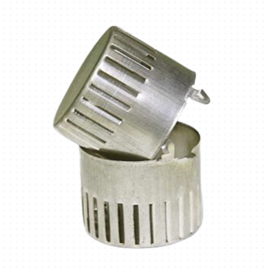
Summary
Wall cracks in deep drawn stainless steel are usually blamed on the die, but the blank, the draw ratio per step and the grade decision are settled before the punch touches the material. This article gives the root-cause sequence we work through at the press, from blank diameter and blank-edge condition to interstage anneal, plus two counter-intuitive levers: going thinner rather than thicker in some austenitic cases, and drawing deliberately longer so the crack lands in material that will be trimmed off.
A wall crack in a deep drawn stainless part is usually reported as a die problem, because the die is where the crack appears. By then, three earlier decisions have already made the failure likely: how the blank was cut, how much reduction each step took, and what the tool does where it contacts the material.
Different causes leave similar-looking tears. A split at the bottom corner, a crack above the die entry and a tear at the top edge point at three different levers. What follows is the order in which we eliminate causes when deep drawn stainless steel cracking appears — cheapest to check at the press first.
Check stainless cracking in this order
The ladder is ordered by cost of correction, not frequency. Items 1 and 2 sit outside the die, in the blank and the process plan, and are the cheapest to verify. Item 7 is a controlled compromise reached only once items 1 to 6 are eliminated.
- Blank diameter, and how the blank edge was produced
- Draw ratio per step, and whether steps were merged for cost
- Punch radius, die radius and radial clearance
- Lubricant type, viscosity, dwell time, and die coating
- Interstage anneal — whether it is performed, and in what atmosphere
- Grade and thickness, including the option of going thinner
- Deliberate over-draw and trim, so the crack forms in scrap
A crack at the same station on every stroke points to items 1 to 4. An intermittent crack, or one that appears only after a few thousand strokes, points to items 4 to 6: heat build-up, lubricant breakdown, or a die surface picking up material.
1. Blank diameter and blank-edge condition
Blank diameter sets the draw ratio directly. An oversize blank asks the wall to reduce more than the grade can carry in one step, and the crack opens below the die radius on the first draw. An undersize blank leaves too little material, and the operator compensates with blank-holder force, converting a height problem into a tear. Put the trim allowance on the engineering drawing: an undocumented allowance is why a part that ran for months cracks after a tool repair.
Blank-edge condition is the cause most consistently overlooked. Trial blanks cut by wire EDM have cracked during drawing and then been mixed into a small production batch, turning a bench trial into a quality escape. Wire EDM leaves a recast layer on the cut face that is hard and brittle, and it fails before the parent metal reaches its forming limit. A heavy burr or insufficient blanking clearance does the same. Burr direction matters: the burr should face away from the die radius so the sharp edge is not dragged through the forming zone. The stainless steel deep drawn parts guide covers the same point from the material side.
The right question is not whether the blank was sheared but what the blanking standard is: clearance as a percentage of thickness, burr height limit, and whether trial blanks come from the production blanking tool.
| Blanking method | Edge condition produced | Cracking risk in the draw | Where it fits |
|---|---|---|---|
| Wire EDM | Recast layer and heat-affected zone on the cut face; no burr | High — the hard layer cracks before the parent metal yields | Prototype geometry only, and even then the edges should be dressed or annealed before drawing |
| Die or turret punching | Sheared edge with controlled clearance, small directional burr | Low to moderate — predictable once clearance and burr limits are specified | Production blanks; the reference method for any part with a released drawing |
| Laser cutting | Oxidised or dross-affected edge, narrow heat-affected zone | Moderate — depends on assist gas and power, and whether the edge is cleaned | Low-volume and thick blanks; verify edge hardness before committing to a hard draw |
| Waterjet | Clean, cold-cut edge with a slight taper | Low, provided the abrasive garnet is removed | Thick or heat-sensitive blanks where no thermal edge is acceptable |
2. Draw ratio per step, and what merging steps actually does
For a cylindrical cup, low-carbon steel tolerates roughly 40 to 45 percent diameter reduction in the first draw. Austenitic stainless sits lower, commonly 30 to 38 percent, because it work-hardens steeply and reaches a higher flow stress at the same strain. Redraws are less aggressive, typically 15 to 25 percent. These are starting points, not limits: the real window depends on grade, thickness, radius and lubrication. Where a step is over-loaded, the tear appears above the die radius on that step, identifying the culprit station.
Merging two redraws into one to save a station is a common cost decision, and it is worth knowing how it fails. In one case it did not crack the part at all: it produced an oversized head radius and a die that would not hold size. A draw that has exhausted material ductility reports as a fracture; a draw that has run out of forming limit in a geometric sense reports as an out-of-tolerance radius, a wrinkled flange or an unstable tool. If the radius will not come in, adding a station may fix it; more lubricant will not.
3. Punch radius, die radius and clearance
Radius is the easiest cause to confirm, because the crack location identifies it. A crack radiating from the bottom corner is a punch-radius problem. A vertical or diagonal crack just above the die entry is a die-radius or clearance problem. A tear starting at the top edge and following the flange is a blank-holder or material-flow problem. Increasing a die radius lowers local strain but also reduces flange restraint, so it can trade a crack for a wrinkle.
Clearance for austenitic stainless is set wider than for carbon steel: about 8 to 12 percent of thickness per side, against 5 to 8 percent for mild steel. Too tight a clearance irons the wall on every stroke and raises punch load and temperature at the die radius, finishing as a tear with visible pick-up. Too loose lets the wall wrinkle; if that wrinkle is ironed flat in the next station it becomes a fold that cracks. Clearance and ironing intent must be decided together, which is why ironing in deep drawing is not a separate topic from cracking.
4. Lubricant, dwell time and die coating
Austenitic stainless galls in a way carbon steel does not. Its surface oxide is thin and does not survive the contact pressure at the die radius, so bare metal contacts bare metal, micro-welds form, and material transfers to the die. The first sign is a dull smear on the wall; the tear follows shortly after. A crack treated as a ductility problem when it is a friction problem will not respond to tool rework, so this belongs with the other entries in a metal working defects review.
Measures that matter more than lubricant brand: a chlorine-free extreme-pressure lubricant intended for stainless, at the higher end of its viscosity range; a measurable dwell at bottom dead centre so the film can re-form; TiN, TiCN, hard chrome or DLC-type coating on punch and die; and the die radius polished along the direction of material flow rather than across it. Keep blank-holder force at the lowest value that suppresses wrinkling, because extra hold-down adds friction where the wall is already thinning. In a progressive die, check delivery per station: the first draw gets adequate oil while the redraw where the crack appears gets only what runs past.
5. Interstage anneal: is it happening, and is it vacuum?
Austenitic grades work-harden steeply. A 304 cup that forms comfortably on the first draw may reach 350 to 450 HV after two redraws, at which point the remaining ductility is small and the next step tears. Interstage anneal restores that ductility and widens the forming window, and it is the right answer when cracking appears only on later stations. The question is not whether the routing lists an anneal, but whether it is performed on the actual parts, at the recorded temperature, with a hardness check or coupon to prove it, and in a vacuum or protective atmosphere. Air annealing leaves scale that must be removed, and pickling adds handling risk on thin walls.
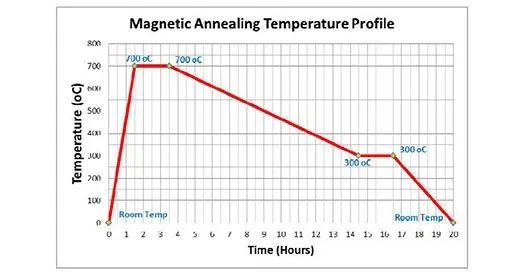
Non-magnetic austenitic grades carry an extra anneal for a second reason: it restores the non-magnetic condition. 304 and 316L are non-magnetic in the annealed state but become slightly magnetic after cold working, because deformation martensite forms in the strained regions. For a sensor housing or a solenoid valve housing that shift is functional, not cosmetic, so the final anneal becomes a product requirement as well as a formability measure. Heat treatment therefore has to be specified with the drawing steps, not appended afterwards.
6. Grade and thickness — including the counter-intuitive 'go thinner' lever
Grade selection decides how much forming window exists before any tool is cut, so the choice should be made with the stainless steel material data in hand rather than by habit.
| Grade | Family | Magnetism | Deep drawing behaviour | Anneal requirement |
|---|---|---|---|---|
| 304 / 1.4301 | Austenitic | Non-magnetic annealed; slightly magnetic after cold work | Good ductility but steep work hardening; the common default for drawn housings | Interstage anneal on multi-step draws; final anneal if magnetic behaviour matters |
| 316L | Austenitic | Non-magnetic annealed; slightly magnetic after cold work | Slightly higher flow stress than 304 and more prone to galling | Same as 304, with more attention to lubrication |
| 430 | Ferritic | Magnetic at all times | Lower work hardening than austenitic, but lower elongation and prone to ridging on heavy draws | Rarely needed for formability; still required for some corrosion or finish conditions |
| 310S | Austenitic, high alloy | Non-magnetic annealed | Very high temperature and oxidation resistance, but high flow stress and material cost | Extra anneal step; specify only where service temperature demands it |
Thickness is where the counter-intuitive decision appears. One real case involved 310S sheet at 0.5 mm, where the drawn part cracked and also showed inner and outer diameter problems. The shop asked for 0.45 to 0.48 mm instead — thinner, not thicker — and that is not a mistake. The mechanism is restraint, not strength. At 0.5 mm, suppressing flange wrinkling requires a blank-holder load that, divided over a thin section, produces a high through-thickness compressive stress and high friction drag on the flange. Reducing thickness lowers the hold-down load needed for the same wrinkle suppression, reduces the through-thickness stress gradient, and lets material flow into the die instead of being pinned and stretched. Thinner sheet also bends more easily around a given die radius, lowering local strain there.
Be clear about when this applies. Going thinner helps when the crack is restraint- and friction-driven and the finished part still tolerates the reduced section; the reduction must also stay inside the drawing tolerance, which is why thickness should be called out as a range where the forming window is tight. It does not help when the wall is already too thin to carry the punch load, or when the grade's elongation is simply too low. Thickness is a lever to test on a trial, not a rule to apply in advance.
7. Over-draw and trim: make the crack land in material you will cut off
The most useful remedy in this sequence is the least obvious. Instead of eliminating the failure, make it happen somewhere harmless: draw the part deliberately longer than the finished component, so that localised thinning or an incipient crack forms in the extra length above the trim line, then cut that length off. The finished part comes from material that never reached the failure strain, and the draw can be run at a level that would otherwise scrap the part. The technique came out of a real production problem and is a production strategy, not a bench trick.
When over-draw and trim is the right answer: It requires three conditions: a trimming operation already exists, the extra material allowance is acceptable, and the crack stays local rather than propagating into the retained wall. It does not apply to a net-shape part with no trim allowance, and it does not fix a blank-edge or lubrication problem — it only converts a marginal forming window into a usable one.
The die engineer must know where the failure would occur and place the trim line below it with margin. A draw force estimate before the tool is cut shows how close the operation sits to the limit; the deep draw stamping materials guide sets out how grade and thickness enter it. The same logic explains a behaviour that confuses buyers: a part can be manufacturable at a longer developed length and impossible at the exact finished height, because the failure strain moves out of the retained section.
When flanging a stainless tube should be replaced by deep drawing
Flanging the end of a stainless tube cracks it. The tube wall has already been cold-worked during tube manufacture and has little remaining elongation, and a flange concentrates almost all of the required strain into a narrow band at the end of the wall. With no annular path for flow, the flange forms by stretching rather than drawing, and the outer fibres of the bend reach fracture strain first. A cut tube end with burr or a partially sheared face makes it worse. The same geometry produced by deep drawing behaves differently: the flange forms from blank material that flows inward along an annular path and can be annealed between the draw and the flange forming.
The decision rule is simple. If the part has a closed end, or a flange on a barrel that is short relative to its diameter, requote it as a deep drawing rather than a flanged tube. If the geometry is genuinely a long thin-walled body with no closed end, tube remains more economical — but specify annealed tube, control the end-cut edge, and keep the flange radius generous and the flange height as short as the joint allows. Where a tube is unavoidable and the flange is wide, a two-stage approach (a small pre-flange, then flattening) distributes strain better than a single strike. Deep draw metal stamping capability and press tonnage decide whether the drawn alternative exists.
Symptom, likely cause and countermeasure
Use the table below as the working map: the symptom column describes where the crack is, and the cause column names the ladder item that most often produces it.
| Symptom | Likely cause | Countermeasure |
|---|---|---|
| Vertical crack in the wall just above the die radius, first draw | Blank diameter too large for the grade, or die radius too small | Reduce blank diameter to the developed size; increase die radius within the flange-wrinkle limit |
| Crack radiating from the bottom corner | Punch radius too small for the thickness | Increase punch radius, or reduce thickness and re-check the corner strain |
| Crack on a later redraw only, after several steps | Work hardening exhausted; interstage anneal missing or ineffective | Add or verify interstage anneal with a hardness check; lubricant alone will not fix it |
| Crack accompanied by pick-up, smear or scoring on the wall | Galling: unsuitable lubricant, no die coating, tight clearance | Chlorine-free EP lubricant at higher viscosity, TiN or hard chrome coating, open clearance to 8-12 percent per side |
| Intermittent cracking after a few thousand strokes | Heat build-up, lubricant breakdown, die or blanking-tool wear | Check die temperature and lubricant delivery per station; measure blank diameter and burr against the blanking standard |
| Cracks confined to trial or low-volume parts | Wire EDM or laser blank edges with a hardened or recast layer | Cut trial blanks on the production blanking tool, or dress and anneal the trial edges |
| Tear starting at the top edge and following the flange | Excessive blank-holder force or insufficient flange material | Reduce hold-down to the minimum that controls wrinkling; re-check developed blank diameter |
| No crack, but head radius oversize and the die will not hold size | Two draws merged into one; forming limit reached in a geometric sense | Restore the separate redraw; this is not a lubrication or anneal problem |
| Flange cracks on a tube end | Pre-cold-worked tube wall with no annular flow path | Requote as a deep drawing, or use annealed tube with a two-stage flange |
Two habits make the ladder work. Record blank diameter, anneal record and lubricant batch alongside the tool for each run. And when a crack appears, measure the blank before opening the die — the most common finding is that the die was fine and the blank was not.
Related reading on deep drawn stamping
These companion notes go deeper on the same engineering decisions:
- DC01 vs DC04 vs SPHC vs SPHE: Which Grade?
- Plating a Deep Drawn Housing: Thickness vs the Tolerance Budget
- The Deep Drawing DFM Checklist Before Cutting Steel
- Interstage Annealing Distortion in Deep Drawn Parts
FAQ: FAQ: Deep drawn stainless steel wall cracking
Q: Why does deep drawn stainless steel crack when the same part in carbon steel runs without problems?
A: Austenitic stainless work-hardens much faster and reaches a higher flow stress at the same strain, so the usable forming window per step is narrower — roughly 30 to 38 percent diameter reduction in the first draw rather than 40 to 45 percent. It also tends to gall against tool steel far more readily than carbon steel, and it may need interstage annealing that a comparable low-carbon part does not.
Q: Can a thinner stainless blank really reduce cracking?
A: In restraint-driven failures, yes. A thinner blank needs less blank-holder force for the same wrinkle suppression, which lowers the through-thickness compressive stress and the friction drag on the flange, and it bends more easily around a given die radius. It only works when the crack is caused by restraint rather than by an insufficient section to carry the punch load, and the reduced thickness must still satisfy the drawing tolerance and the part's structural requirement.
Q: What is the over-draw-and-trim technique?
A: The part is drawn deliberately longer than the finished component so that localised thinning or an incipient crack forms in the extra length, which is then trimmed off. The finished part is taken from material that never reached the failure strain. It requires an existing trim operation, an acceptable extra material allowance, and confidence that the crack stays local rather than propagating into the retained wall.
Q: How do I tell whether the fault is the blank or the die?
A: Measure blank diameter, blank-edge burr and edge hardness first, and check whether trial blanks came from the production blanking tool or from a wire EDM machine. Wire EDM leaves a recast layer that cracks before the parent metal yields. If blank diameter and edge condition are within the drawing and the crack still appears at the same station, the cause is in die geometry, clearance or lubrication.
Q: Why does flanging a stainless tube end crack, and what is the alternative?
A: Tube walls are already cold-worked during tube manufacture, and a flange concentrates nearly all required strain into a narrow band with no annular material flow, so the outer fibres reach fracture strain first. Producing the same geometry by deep drawing gives the flange an inward flow path and allows an anneal before flanging. Tube remains the better route for long thin-walled bodies with no closed end.
Q: Do 304 and 316L stay non-magnetic after deep drawing?
A: They are non-magnetic in the annealed state but become slightly magnetic after cold working, because deformation martensite forms in the strained regions. For sensor or solenoid valve housings where magnetic behaviour is functional, the degree of cold work and the final anneal become product requirements rather than forming considerations.
Q: Is merging two draws into one a reliable cost saving?
A: Only when the merged step stays inside the forming window. When it does not, the failure signature is usually geometric rather than a fracture: an oversized head radius, a wrinkled flange or a die that will not hold size. If that is what you see, restoring the separate redraw is the fix, and lubrication changes will not help.