Summary
A deep drawing DFM checklist is the set of engineering questions a supplier resolves before any die steel is cut: corner radii, ID and OD coupling, steel formability, the height-thickness-draw-step trade, wall thinning and feature placement. Resolving them at quotation turns them into a written change request; resolving them later turns them into new inserts, new blanks and rejected lots. This is the checklist, the reason behind each item, and what it costs when the item is ignored.
What a deep drawing DFM review is, and when it happens
A design-for-manufacture review is the stage between receiving an enquiry and cutting the first block of die steel. We take the 2D drawing, the 3D model and the material callout, and work through what the press can do with the geometry: whether the draw ratio fits the number of stages we will build, whether the internal radii can form without tearing, whether the wall will thin past the tolerance band, and whether features on a formed wall can be made there at all.
The output is one of three things. If the part is straightforward, we quote it. If it is marginal, we quote it with a change request listing each deviation and the consequence of not accepting it. If the geometry is not a drawing part at all - a machined part, an assembly, or something needing a process we do not run - we say so instead of quoting a number that will not hold.
This stage is sometimes treated as a formality. Every item below becomes more expensive to fix once the die exists: a radius change costs a drawing revision before the die is cut, and a new insert after.
The checklist, item by item
The table below is the checklist in the order we run it. Each row is a question we ask about your part, the reason behind it, and what it costs if the item is left unresolved.
| DFM item | What we ask | Engineering reason | Consequence if ignored |
|---|---|---|---|
| Internal corner radius | Increase internal radii to a 1.0 mm minimum on a drawn box | Tight radii concentrate strain at the corner and can demand an extra redraw stage at a smaller punch radius | Cracking at the corner, or an additional draw stage and die station |
| ID, OD and wall callouts | State which of the three is functional and relax the other two | Wall is half the difference between OD and ID, so three tolerance callouts sit on two degrees of freedom | The wall drifts out of band or the diameter does, and parts fail on the dimension nobody marked critical |
| Steel grade | Accept a more formable grade if the draw depth requires it | Lower carbon and a higher plastic strain ratio let the material stretch further before it tears at the die radius | Draw splits, or an intermediate anneal added between drawing stages |
| Part height | Reduce height, or accept one more draw stage | Height is what drives the number of draws; the stage count is an output, not a starting assumption | An underestimated stage count becomes a requote after tooling has begun |
| Starting thickness | Accept a thicker blank, or accept a wider wall tolerance | Thicker material draws further before thinning out, but it raises blank force and die load | Wall thinning past the drawing limit, found at first-off instead of at quotation |
| Feature placement | Move the feature off the formed wall onto a machined face, or the reverse | Punching into a formed wall accelerates local die wear and lets the wall drift over the tool life | Wall thickness changes as the die wears and the feature drifts with it |
| End condition | Accept a part drawn deliberately long with a trimmed end | A crack or burr is placed in material that is removed afterwards | The defect lands on the finished profile and the whole draw is scrapped |
| Tooling reuse | Tell us which detail features repeat across the part family | Identical recessed hole details and seat profiles can share tooling | Tooling bought that did not need to be bought, plus a longer tooling lead time |
| Units and standards | Confirm metric or imperial and which drawing standard governs the part | A conversion error shifts every dimension in the same direction | A total reject rate on one characteristic rather than a normal scatter of defects |
Two rows deserve separate treatment: the corner radius, because it has a hard published floor, and the ID/OD/wall coupling, because buyers most often assume it is free.
The internal corner radius floor: R1.0 mm at all corners
The figure we quote most often is a minimum internal radius of 1.0 mm at all corners of a drawn box - both between the bottom and the walls, and between adjacent walls. That is the floor we can guarantee, not a preference. Bring a 1.0 mm corner and it is a known quantity in the die. Bring a 0.5 mm corner and one of two things happens: the corner needs an extra redraw stage at a smaller punch radius, or the strain exceeds what the material can take and the shell splits.
A split is not a slow degradation. It is a hard failure at first-off, or after a few thousand strokes, depending on where the material's forming limit sits relative to the tool. That uncertainty is what makes tight corners expensive rather than difficult.
The floor is both material- and depth-dependent, so treat 1.0 mm as a conservative published figure rather than a law. A shallow aluminium or brass shell can sometimes hold a tighter corner. A deep austenitic stainless shell with a high height-to-diameter ratio generally cannot, because 304 work-hardens steeply and the corner is where strain concentrates. A design needing a genuinely sharp internal corner is better served by a machined or coined detail after drawing. Related failure modes are collected under metal working defects.
ID, OD and wall: choose which two are functional
Wall thickness on a drawn shell is not an independent variable. It is half the difference between the outside diameter and the inside diameter. A drawing calling out a tight ID, a tight OD and a tight wall is asking for three tolerances on two degrees of freedom, and one will give. Usually the wall wanders inside its band while the diameter stays put, or the reverse - and the inspection argument is about which dimension the designer cared about.
Our question at quotation is simple: which of the three is functional? If the part is a bearing seat, the ID governs and the wall can breathe. If it presses into a bore, the OD governs. If it sits in a magnetic circuit, wall thickness may matter because it sets the flux path. Tell us which one and mark it on the drawing; we will hold it while the other two float inside a band stated in the quote. Framed dimensions are the critical ones and the ones a future PPAP is built on; how we read that convention is in the engineering drawing guide.
Wall thinning: an 85 percent assumption against a 75 percent reality
When a drawing states a wall thickness for a drawn section, that number is the finished wall, not the blank thickness. The blank has to start thicker, because drawing thins the material as it flows over the die radius and down into the wall. How much it thins depends on the draw ratio, the grade, the lubrication and the number of stages - and this is where a quotation can quietly go wrong.
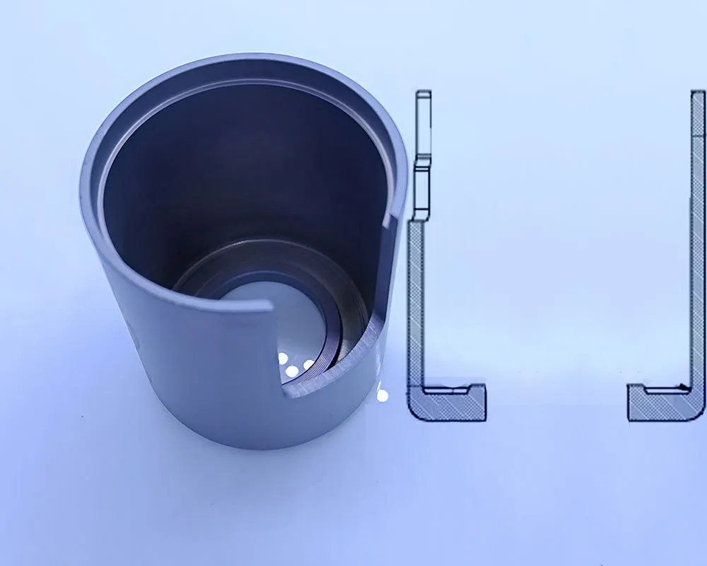
In one review the working assumption was that the wall would finish at about 85 percent of original thickness, and the process analysis said the achievable figure was closer to 75 percent. On a 1.0 mm blank that is a ten-point gap: 0.85 mm assumed against 0.75 mm achievable. On a wall callout of plus or minus 0.05 mm, that gap decides whether the blank has to start thicker. What matters is when it surfaces - caught at quotation it is a change request, caught after tooling it is a new blank specification and new die clearances.
Where the finished wall must be tight, ironing narrows the gap between the drawn wall and the specified one. It also adds a station, so it has to be priced and planned rather than reached for at first-off. The mechanics are covered under ironing in deep drawn stamping.
Height, thickness and the number of draw steps
There is no single correct number of draws for a part. There is a trade surface between three variables: finished height, starting thickness and number of drawing stages. Move one and the other two move with it, and a quote is a statement about where on that surface the process landed.
A concrete example. A buyer asked what the minimum starting thickness would be if the part height came down by 20 mm, then 30, 40 and 50 mm. The answer across that whole band was that the thickness requirement barely moved, because the reduction took the part from two deep drawing steps to three. The height saving was real; so was the extra stage - one more die station, one more press stroke per part, one more operation where the wall can thin. Shorter is usually cheaper, but the step change is what costs, not the millimetres.
The mirror case is merging draws. Taking two drawing operations down to one is possible on paper and usually fails in the press: the head radius comes out oversized because the material has to travel too far in a single hit, and the die is not stable enough to reproduce the geometry. That is a different failure signature from cracking - the part does not tear, it does not come out the same twice.
Related to this, an R dimension on a drawn part does not reach its final size in one hit. Radii accumulate across the draw sequence, and adjusting an intermediate radius to correct the final profile also changes the overall length. That is why a sample can come back slightly long while every individual radius complies. The mechanics are in deep drawing technology explained.
The steel grade ladder: DC01, DC04, SPHC, SPHE
Carbon content is the first thing we look at when the draw is deep. Higher carbon means higher yield strength and lower ductility, so the material resists flow and tears earlier at the die radius. The practical substitution ladder, from least to most formable, runs DC01 to DC04 to SPHC to SPHE - and to SPHF where the draw ratio is close to the top of what the process can do at all.
Two caveats belong with that ladder. First, it is a ladder of formability, not of quality. DC01 and DC04 are cold-rolled drawing grades with good surface and tight thickness control, while SPHC and SPHE are hot-rolled grades that form well but arrive with a coarser surface and a wider thickness band. Moving from a cold-rolled to a hot-rolled grade can make the draw possible and make the surface specification harder to meet in the same decision. The choice is driven by three things together - draw depth, required surface, and the thickness band the part can tolerate. Aluminium, copper, brass and the austenitic stainless grades sit on their own scales, covered in the deep draw stamping materials guide.
The austenitic stainless note is the counter-intuitive one. Drawing SUS304 or 316L work-hardens the material, and strain-induced martensite in a heavily drawn 304 wall can leave the finished part weakly magnetic and, at high reduction, prone to delayed cracking. In those cases a thinner starting sheet with more stages, or an intermediate anneal, can be more robust than a thicker sheet drawn in fewer hits. Thicker is not automatically safer.
Formed wall or machined face: where a feature belongs
Some features cannot live on a formed wall, and some should not. A step, groove or seat that must stay dimensionally stable for the life of the die is usually better on a machined face, because a machined surface does not move as the die wears. A feature that only has to exist, and whose position does not govern function, can often be punched into the wall.
We have seen this decision move in both directions. In one case an internal step had to be moved out of machining and into punching, because the machining operation was disturbing the wall. In another, a feature moved from punching into machining, because punching the formed wall accelerated local die wear and let the wall drift over the production run. Both changes were expensive, because both were discovered after the process had been fixed. The question belongs in the DFM review, where the answer is still a design decision.
A useful rule of thumb: if a feature's tolerance is tighter than the wall tolerance it sits on, it does not belong on the wall. Either loosen the feature or move it to a surface machined after forming.
Capability boundaries: what we decline, and why
A design review is only useful if the reviewer states its own limits. These are the boundaries we apply, stated specifically, because a general answer that we can do most things wastes your time and ours.
| What is asked for | Our position | Why |
|---|---|---|
| A drawn part that also requires a welded joint | Declined | There is no welding process in this plant for these parts; the scope is stamping plus simple machining only |
| A coiled stator or vertical-wound core | Declined, or quoted without sampling | The geometry cannot be sampled on the equipment we run, and we will not quote a part we cannot prove out |
| A thin-wall part with a leak-tight seat | Quoted only if no tool marks will show at 10x magnification | A seat that leaks because of a mark is a functional failure, not a cosmetic one |
| A part whose geometry is essentially a machined part | Declined as drawing work | Quoting it as a draw would produce a tool that cannot hold the geometry, or a part that should have been machined |
| A drawn shell held to a 0.02 mm dimensional band | Quoted with an explicit confidence caveat | That band is not achievable with full confidence on a drawn feature; stating so up front beats a rejected lot |
| An internal corner tighter than 1.0 mm on a deep box | Reviewed case by case against the 1.0 mm floor | Below the floor the choice is an extra draw stage or a crack risk, and the material decides which |
These boundaries pre-qualify an enquiry. If a part falls into a declined row, the answer is a clear no rather than a quote that unravels later - worth more to a project schedule than a number that looks competitive. The boundaries are not brittle either: a thin-wall part with a leak-tight seat is an ordinary job when the surface route is agreed at quotation, whether that is a polished insert, bead blasting or electropolishing. Our wider position on scope is under capability boundaries.
Traps, tooling sharing, and what to send us
Traps that only appear after the die is cut
Three failures recur, and all three are avoidable at the review stage. The first is a feature the drawing omits entirely - a fillet nobody dimensioned, so it was never designed into the die. The second is an internal feature that has to move between punching and machining after the fact, because die wear changed the wall and the original process no longer holds the dimension. The third is a unit conversion error: a dimension given in imperial units and read as metric made every part fail one limit, consistently and in the same direction.
That last pattern is worth recognising on its own. A uniform failure on a single characteristic, with everything else in band, is the signature of a units or standard mismatch rather than a process problem - and it should be checked before anyone adjusts the die.
Tooling sharing is a question worth asking
If two parts in a family share a recessed hole detail, a groove profile or a similar seat, ask whether the tooling can be shared before the quote is fixed. It is one of the few items where the supplier's answer improves the job, and buyers raise it themselves. It is best asked with a part family list attached, so the overlap is visible across the set.
What to send us for an accurate DFM review
- A 2D drawing with full tolerance callouts, including which dimensions are critical - the framed or boxed dimensions on your drawing.
- The 3D model in STEP or IGES, so the draw ratio and corner geometry can be checked rather than inferred from views.
- The material specification and grade, plus any surface, plating or heat-treatment requirement.
- Annual volume and the expected batch pattern, because both feed the tooling and process decision.
- A note on which dimensions are functional and which are free - the ID, OD and wall question in particular.
- If the part belongs to a family, the other drawings, so that tooling sharing can be assessed before the quote.
Before you send: Six items, one message. With all six the review is a matter of days; with a single PDF and no material callout it becomes a correspondence round that delays the tooling decision.
If you are comparing suppliers on how they handle this stage, the questions in how to evaluate a metal stamping supplier are the right ones to ask, and our deep draw metal stamping capability page states the equipment envelope the review works inside.
Related reading on deep drawn stamping
These companion notes go deeper on the same engineering decisions:
- How Many Draw Steps Does a Part Need?
- Deep Drawn vs Welded Housing: Is It Actually Sealed?
- Interstage Annealing Distortion in Deep Drawn Parts
- Inspecting Deep Drawn Parts: Radius, Runout, Concentricity
FAQ: FAQ: Deep Drawing DFM and Design Review
Q: What is a deep drawing DFM checklist?
A: It is the set of engineering questions a supplier resolves between receiving a drawing and cutting die steel. The core items are internal corner radii, the ID and OD and wall tolerance stack, steel grade formability, part height against the number of draw stages, starting thickness against achievable wall thinning, and whether each feature belongs on a formed wall or a machined face. The output is a quote, or a quote plus a written change request.
Q: What is the minimum internal corner radius for a deep drawn box?
A: 1.0 mm is the floor we can guarantee, both between the bottom and the walls and between adjacent walls. Below that the corner either needs an extra redraw stage at a smaller punch radius or it becomes a cracking risk. The real limit depends on material and depth: a shallow aluminium or brass shell may hold tighter, while a deep SUS304 shell with a high height-to-diameter ratio generally will not.
Q: Can you hold a tight ID, a tight OD and a tight wall thickness at the same time?
A: Not independently. Wall thickness is half the difference between OD and ID, so three callouts describe two degrees of freedom and one of them has to float. Tell us which of the three is functional - a bearing seat points to the ID, a press fit points to the OD, a magnetic circuit may point to the wall - and we will hold that one while the other two move inside a band stated in the quote.
Q: How much wall thinning should I expect in deep drawing?
A: It depends on draw ratio, grade, lubrication and the number of stages, but the gap is larger than most drawings assume. In one review the drawing implied a wall at about 85 percent of original thickness while the process could hold roughly 75 percent, which is a ten-point difference on a 1.0 mm blank. Where the finished wall is tight, an ironing operation can close part of that gap at the cost of an extra station.
Q: Will changing the steel grade let you make my part?
A: Often, yes. Carbon content drives formability, and the practical ladder from least to most formable runs DC01 to DC04 to SPHC to SPHE. It is a formability ladder rather than a quality ladder: the DC grades are cold-rolled with tight thickness control and good surface, while SPHC and SPHE are hot-rolled and form well but with a coarser surface and wider thickness band. The choice is a trade between draw depth, surface requirement and thickness tolerance.
Q: Do I have to accept every design change you request?
A: No, but the item has to be resolved one way or the other before tooling starts. Each change request states what is being asked, the engineering reason and the consequence of not accepting it. Sometimes the answer is to keep the design and accept the extra draw stage, the additional annealing step or a wider tolerance band. What we avoid is leaving it open until first-off, when every option costs a die modification.
Q: What happens if the DFM review finds a problem after tooling has already started?
A: It becomes a tooling change rather than a design decision, which is the expensive version. A radius change moves from a drawing revision to a new insert or an extra station, and a wall thinning shortfall moves from a blank thickness decision to a new blank specification, new die clearances and a re-qualification. This is why the review is run at quotation, alongside the first cost estimate.