
When Progressive Die Stamping Makes Sense
Progressive stamping is generally considered when a part requires multiple operations in a repeat-production program and the material can remain attached to a strip carrier through the tooling sequence.
High Production Volume
Dedicated tooling is easier to justify when annual demand is repeatable.
Multiple Features
Blanking, piercing, forming and other operations can be integrated into one progressive tool.
Consistent Part-to-Part Output
Indexed strip feeding supports repeatable positioning and process flow.
Lower Secondary Handling
In-die operations can reduce separate handling and downstream processing.
What We Make with Progressive Stamping
Real part families produced through our progressive stamping programs — each links to the relevant application or case page.
Shims & Washers
Precision-blanked shims and washers with controlled profile and flatness.
Lock Plates
Stamped profiles with locking features for mechanical assemblies.
Brackets
Blanking, piercing and forming combined with controlled bend location.
Terminals & Clips
Conductive terminals and clips with controlled material and geometry.
Sensor Components
Small functional parts for sensor assemblies where feature location drives performance.
Valve Components
Formed valve parts and spring-related components for fluid or magnetic systems.
Small Formed Housings
Compact drawn and formed housings where strip-fed integration is practical.
Retainers
Formed retainers and spring seats with consistent depth and feature relationships.
How Progressive Die Stamping Works
A progressive die feeds strip material through multiple stations. Blanking, piercing, bending, forming, drawing or other operations are arranged in sequence while the strip remains under controlled feed and carrier guidance.

Strip Layout and Station Planning
The strip layout determines how the material moves through the die, how features are distributed across stations and how efficiently the available material is used. Station sequence, carrier design, material utilization, pilot guidance and feature timing are reviewed before tooling is released.
WHY TOOLING DESIGN MATTERSWhy Tooling Design Matters
Station sequence, strip carrier, pilot guidance, punch clearance, material flow, strip support and part transfer define whether a part runs repeatably. Balford's in-house toolroom designs progressive dies internally, working with established tool steel suppliers and TD/PVD coating partners.
In-Die Tapping for Integrated Thread Formation
In-die tapping forms threads directly inside the tool while the strip is indexed. It eliminates a separate tapping operation downstream, giving threads that are concentric with the pierced hole and hold true positional tolerance — fewer secondary operations, less handling and a cleaner documentation submission.
Choosing the Right Stamping Tooling
Four tooling routes solve different manufacturing problems — none is universally "better". The comparison below is engineering guidance, not an absolute rule.
Progressive Die
Strip-fed, multi-station tooling for repeat parts with integrated operations.
Compound Die
Multiple cutting operations in one press stroke at one station — well suited to cutting-dominated flat parts.
Transfer Die
Individual blanks move between dedicated stations — useful when geometry or forming depth makes strip-fed progressive tooling less practical.
Conventional Single-Operation Stamping
Simpler geometry, lower tooling complexity or project-specific requirements.
| Tooling Type | Best Fit | Typical Strength | Main Limitation |
|---|---|---|---|
| Progressive Die | High-volume strip-fed parts with multiple stations | Integrated operations and repeatability | Dedicated tooling and strip layout required |
| Compound Die | Multiple operations in one press stroke | Compact tooling and reduced re-fixturing | Not ideal for every multi-stage or 3D part |
| Transfer Die | Larger / deeper parts requiring separate stations | Flexible multi-stage forming | More complex transfer system |
| Conventional / Single-Operation | Lower-volume or simpler parts | Lower initial tooling complexity | More handling and separate operations |
The right tooling route depends on part geometry, annual volume, material, tooling investment, operation sequence and secondary processing — not a fixed volume threshold. Different tooling routes solve different manufacturing problems; none is universally "better".
Progressive Stamping Materials
Material grade, temper, thickness and surface condition affect the strip layout, tool clearance and forming sequence.
Carbon Steel
Common for brackets, washers, lock plates and structural parts.
Spring Steel
Shims and functional parts where hardness and temper are controlled.
Stainless Steel
Corrosion-resistant parts with controlled work hardening and burr formation.
Aluminum
Lightweight parts where alloy and temper affect forming behavior.
Copper
Conductive terminals and parts with controlled surface condition.
Brass
Formable option for conductive or appearance-critical parts.
Special Alloys
Selected materials reviewed per drawing before tooling.
All Materials
Grade, temper, thickness and surface condition affect the tooling route.
Applications for Progressive Stamping
Where progressive-stamped components are used across our production programs.
Automotive Components
Lock plates, brackets, sensor parts and formed components for vehicle assemblies.
Sensor Components
Small functional parts where feature position and repeatability drive performance.
Solenoid / Valve Components
Formed valve parts and spring-related components for fluid or magnetic systems.
Electrical Components
Terminals, clips and conductive parts with controlled geometry and surface condition.
Industrial Components
Brackets, guides and hardware made to specific drawings.
Washers & Shims
Flat precision parts with controlled tolerances across materials.
How We Control Progressive Stamping Quality
Quality is planned before steel is cut — tooling, feeding, inspection and material control are treated as one system.
Material Verification
Material grade, thickness and condition are verified against the approved production specification before runs.
In-Process Inspection
First-piece and in-process checks cover critical dimensions and feature position according to the control plan.
Tool / Machine Monitoring
Tooling condition, feeding, setup and process stability are monitored to protect repeatability over the program life.
Final Dimensional Inspection
Final checks verify the drawing requirements; FAI and customer-specific documentation (e.g. PPAP elements, IMDS, RoHS-related records) can be discussed when part of the project requirements.
From Drawing to Progressive Tooling
Balford runs an in-house toolroom that handles all die construction. From order placement to sample delivery, every step of production is monitored closely.
Drawing Review
Material, tolerances, part orientation, critical features, annual volume and downstream operations.
Strip Layout & Process Planning
Carrier design, station sequence, material utilization and feature timing defined before tooling release.
Progressive Die Design
Die architecture built around the forming sequence, guidance, clearance and inspection points.
Tool Build & Sample Validation
Samples run, critical dimensions verified, process adjusted before production release.
Production Release
Validated tool and production controls released for repeat output.
Selected Progressive Die Stamping Case Studies
Real parts, real materials, real manufacturing requirements — projects where stamped profiles, formed geometry and feature relationships were produced in controlled tooling sequences.

Sprocket & Pinion Shaft Nut Lock Plate
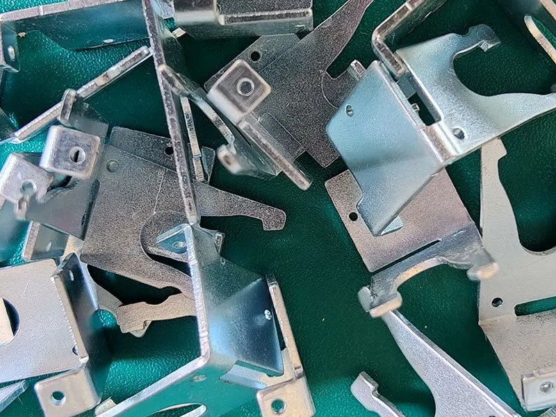
Stamped Metal Bracket

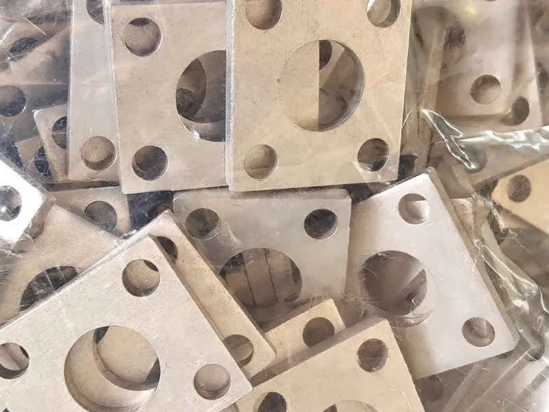
Stainless Steel Nut Washer
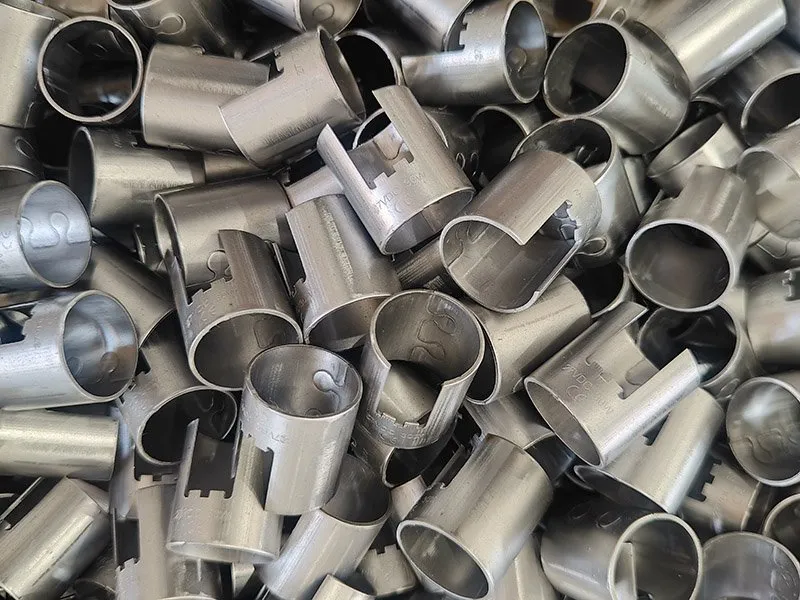
Carbon Steel Slotted Ferrules
D Ring With Backing Plate
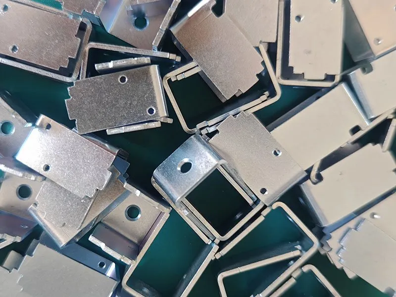
Metal Frame for Open Frame Solenoids
Progressive Stamping Engineering Topics
Supporting technical resources on in-die operations and advanced forming.
In-Die Tapping
Threads formed directly inside the tool — concentric with the pierced hole, with fewer secondary operations.
Micro Deep Drawing
Progressive tooling producing repeatable 3D micro parts from thin metal foil.
Four-Slide & Multi-Slide Stamping
Side punching and multi-direction forming in progressive sequences.
In-Die Rotary Cutting
Rotary cutting integrated into the progressive sequence.
Inside a progressive die line
A small square housing running in a progressive die. For the tapped variant, see in-die tapping.
Progressive Die Stamping FAQ
Direct answers for purchasing and engineering teams — based on our actual tooling and production capabilities.
Progressive stamping keeps the strip attached to a carrier and indexes it through multiple stations. Transfer stamping moves individual workpieces between separate dies or stations — useful when part geometry or forming depth makes strip-fed progressive tooling less practical.
A compound die performs multiple cutting operations in a single press stroke at one station. It can be a practical choice for cutting-dominated flat parts such as washers and discs with closely related features, where multi-station strip forming is not needed.
Consider progressive stamping when a part requires multiple operations in a repeat-production program and the material can remain attached to a strip carrier through the tooling sequence. Repeat volume, operation count, material utilization and automated feed all support the comparison.
Yes, progressive tooling can integrate drawing or forming operations for suitable geometries, provided the material and part design support the required sequence. Drawing is also run as an independent forming process where geometry demands it — see the Deep Drawing capability.
In-die tapping can be integrated where the part and tooling design support thread formation within the progressive sequence — threads formed in the die are concentric with the pierced hole and reduce downstream handling.
Carbon steel, spring steel, stainless steel, aluminum, copper, brass and select special alloys are all practical candidates, depending on grade, temper, thickness and feature requirements. The material specification is confirmed against the drawing before tooling.
There is no meaningful standard price because tooling cost depends on station count, part geometry, material, tolerances, integrated operations and expected production volume. Balford quotes tooling from the actual drawing and production requirements.
Annual volume should be evaluated against tooling cost, cycle requirements and part geometry — there is no fixed threshold. The tooling investment is justified when the part runs repeatedly at sufficient volume and multiple operations can be combined into the strip process.
Send the 2D drawing, 3D model when available, material grade, thickness, annual volume, critical tolerances, surface finish and any secondary operations. The engineering team reviews the tooling route before quoting.
Confidential Project Review
We will sign a Non-Disclosure Agreement (NDA) with our partners to strictly protect the confidentiality of customer drawings, materials and prototypes.
Send Us Your Drawing
For a faster review, send: latest 2D drawing or 3D model, material grade, thickness, annual volume, critical tolerances and surface finish. The engineering team reviews the tooling route before quoting.
Related Capabilities & Resources
Progressive die stamping connects to the full stamping cluster, materials, applications, supplier network and quality resources.
Related: ironing in deep drawing — how a thinned wall holds both the inside and the outside diameter · ironing instead of turning · ironing for solenoid valve housings (DT4E, DC04) · ironing tolerances and surface finish
Not every high-volume part belongs in a progressive die — deeper draws and heavier walls often run better on transfer press tooling. The presses behind this process are listed, with tonnage and maximum draw diameter, on the machinery and equipment list.
Choosing between routes? See deep drawing vs progressive die stamping.
Progressive tooling only pays above roughly 50,000 pieces — below that, single-operation tooling for prototypes and short runs is normally the cheaper route.