Deep Drawn Sensor Housings, Made to Drawing
A deep drawn sensor housing is a seamless metal shell: the wall is pulled from a flat blank instead of welded or machined, so there is no longitudinal seam to leak and no weld to distort the bore. Balford draws and stamps housings for oxygen, NOx, injector, exhaust gas temperature, ABS and motorcycle sensors, plus Denso-style fitment parts and heat shields.
The family this page belongs to is the sensor housing capability, with 398 published catalogue configurations across ten series and dimensions in millimetres. Housings that measure a fluid rather than a gas are on the temperature sensor housing page.

Which Sensor Housings Are Deep Drawn, and Which Are Not
Deep drawing wins where the part is a cup, shell or sleeve and the wall has to be continuous. Where the part is flat and low-profile, stamping is the cheaper route - the table says which family takes which route, and links to the data behind it.
| Sensor family | Forming route | Why that route | Data / catalogue |
|---|---|---|---|
| Oxygen (O₂) sensor housings | Deep drawn stainless shell, stamped shield | A thin drawn wall around a sealed bore suits the volume and the heat cycling; the shield is stamped separately. | Oxygen series (105 configurations) |
| NOx sensor housings | Deep drawn and stamped stainless, 310S for exhaust-side parts | Cyclic high temperature plus condensate is what decides the grade rather than the geometry. | NOx material selection |
| Injector & exhaust gas temperature housings | Deep drawn shell with a machined seal face | The drawn wall carries the pressure cycle and the machined face carries the seal, so the two operations are planned together. | Injector & EGT series (22) |
| ABS / wheel-speed sensor housings | Deep drawn and stamped | The press-fit diameter and the concentricity between bore and outer wall decide whether the sensor seats, so they are treated as critical characteristics. | ABS wheel-speed housing case |
| Motorcycle sensor housings | Small-diameter deep drawing | Small outside diameters on short, tightly packaged parts; the smaller presses and the same draw-die library are used. | Motorcycle series (21) |
| Denso-style fitment housings and heat shields | Stamped and drawn stainless, 430 for flange and shield parts | Compatible fitment parts: the geometry is matched to the drawing or sample, and we do not claim to make original-equipment parts. | Denso-style series (83 across two series) |
| Pressure sensor housings | Formed and drawn, then machined (aluminium 6061 / 5052) | Lightweight bodies where the sealing face is machined after forming to hold the seal. | Aluminium pressure housing case |
The Deep Drawing Route Behind the Part
Six stages run from drawing review to shipped part. Which of them are needed - and whether they run in a progressive die or on single-operation tooling - is decided by the draw ratio and the annual volume, not by the machine list.
| Stage | What happens |
|---|---|
| Blank preparation | Coil or sheet is blanked to the developed size for the draw sequence, with the grain direction recorded because it changes how the wall thins. |
| Draw and redraw | The blank is pulled into the die and reduced over successive stages. Balford runs presses to 350 t and draws diameters to Ø250 mm, so the number of stages is set by the draw ratio rather than by the machine. |
| Inter-stage annealing | Work-hardening grades are annealed between draws so the next reduction does not crack the wall. On high-volume parts this is written into the process plan, not applied as a fix. |
| Trim, pierce and bore | The flange is trimmed, holes are pierced and the bore is cut to the drawing, in the same tool where the volume justifies it. |
| Machining the sealing and press-fit features | The seal face, press-fit diameter, thread or chamfer is turned or milled after drawing, because these are the characteristics that decide whether the housing seals and seats. |
| Surface finish and verification | Passivation or plating is applied per the drawing, then the first article is measured and documented. FAI reports and PPAP-aligned documentation are available for automotive programmes. |
Tooling for every one of these stages is designed and built in-house: in-house tooling design & build. Only slow-wire EDM is subcontracted.
What Decides the Drawing Route
Two housings can look almost identical and quote very differently, because the drawing route is set by six things. These are the questions we work through before any tool is cut, and they are the same questions the DFM review answers in writing.
| Factor | What it changes |
|---|---|
| Draw ratio | How many stages the part needs, and therefore the tooling and the part cost. |
| Wall thickness and ironing | Whether the wall is drawn or deliberately thinned (ironed) to reach the specified thickness. |
| Concentricity and roundness | Whether the bore, the outer wall and the sealing face have to be co-axial within a stated band. |
| Sealing face and press-fit diameter | Whether those features are formed in the tool or machined afterwards. |
| Material grade | 304, 310S, 316L or 430 stainless, aluminium or carbon steel - the grade sets the anneal schedule and the corrosion behaviour. |
| Annual volume | Whether the part runs in a progressive die or on single-operation tooling. |
Where the drawing leaves a characteristic open, we work to ISO 2768-m and flag what should be tightened. The tolerance background is published on the sensor housing tolerance guide and the wall thickness guide.
Materials We Draw for Sensor Housings
| Material | Typical use | Catalogue thickness |
|---|---|---|
| Stainless 304 | General oxygen sensor shields and housings | t 0.4–0.6 mm |
| Stainless 310 / 316 | High-temperature NOx, EGT and exhaust parts | t 0.4–1.0 mm |
| Stainless 430 | Denso-style heat shields and flange parts | t 0.5–1.0 mm |
| Aluminium | Pressure sensors and lightweight housings | per drawing |
| Carbon steel | ABS and structural housings | per drawing |
Grade selection per sensor family is set out on stainless steel for sensor housings, aluminium stamping and deep drawing, and carbon steel.
Catalogue: 398 Configurations Across 10 Series
Every series below is a published set of our own drawings with dimensions in millimetres, and each product can be quoted directly by catalogue code. The same dataset is citable from sensor housing catalogue data.
| Series | Published configurations |
|---|---|
| Oxygen Sensor Housings (B) | 46 configurations |
| Oxygen Sensor Housings (D) | 20 configurations |
| Oxygen Sensor Housings (N) | 39 configurations |
| NOx Sensor Housings | 21 configurations |
| Injector & Exhaust Temp Housings | 22 configurations |
| Denso-Style Fitment Housings | 41 configurations |
| Denso-Style Heat Shields | 42 configurations |
| ABS / Wheel-Speed Housings | 121 configurations |
| Motorcycle Sensor Housings | 21 configurations |
| Other Stamped Components | 25 configurations |
Capacity and Evidence
Sensor housings run on the same presses and the same quality system as the rest of the plant, so the numbers that matter are already published:
- Press capacity up to 350 t and maximum deep draw diameter Ø250 mm - see the machinery and equipment list.
- Tooling designed, machined, wire-cut, welded and tried out in-house - see tooling design & build.
- 12,000 m² factory, 500+ machines, ISO 9001:2015 management system - see quality and certifications.
- FAI reports and PPAP-aligned documentation including IMDS support - see PPAP and automotive material compliance.
The primary process pages are deep drawn metal stamping, precision metal stamping and CNC machining.
Selected Sensor Housing Case Studies
ABS Wheel-Speed Sensor HousingStainless steel, deep drawn, press-fit controlled. Automotive Pressure Sensor HousingAluminium housing, formed then machined.
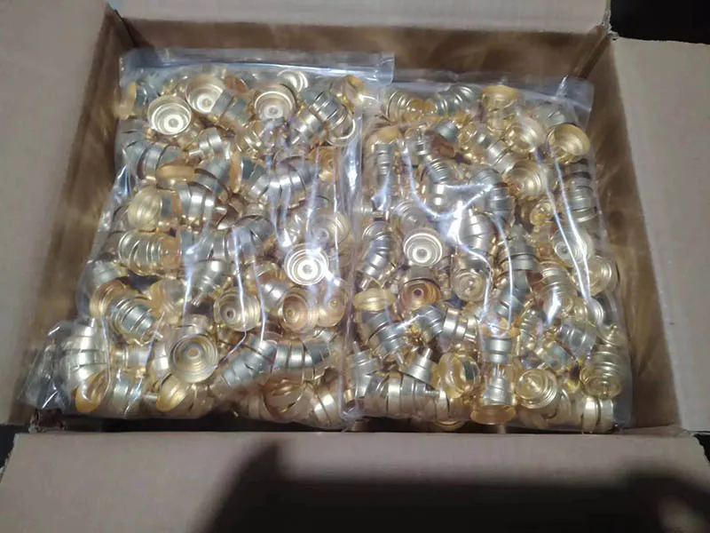 Coolant Temperature Sensor HousingCustom stamped housing for engine temperature sensing.
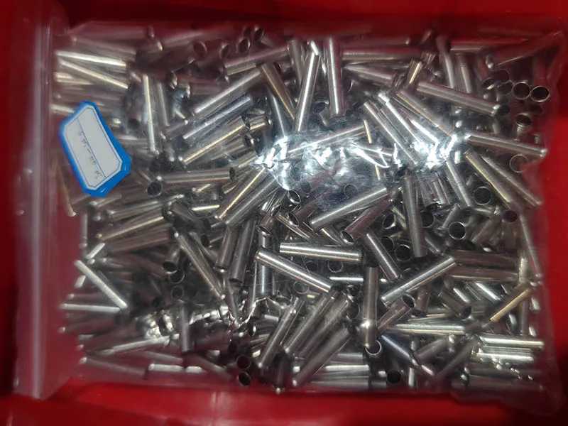 Exhaust Temperature Sensor PipeStainless connecting pipe for EGT sensor harnesses.
Deep Drawn Sensor Housing FAQ
What is a deep drawn sensor housing?
It is a seamless metal shell formed by pulling a flat blank into a die, so the wall has no longitudinal weld and no machined seam. The sensing element sits inside the shell and the drawn features - bore, press-fit diameter, sealing face - position and seal it.
Which sensor housings can be deep drawn?
Oxygen, NOx, exhaust gas temperature and injector housings are normally deep drawn or drawn and stamped; ABS and wheel-speed housings are drawn and stamped; motorcycle and small position sensors use small-diameter drawing; pressure sensor bodies are formed, drawn and then machined. Flat, low-profile parts are better served by precision stamping, and the family table above says which route each one takes.
What wall thickness and tolerances can you hold?
Sensor housing walls are typically 0.3–1.0 mm, set by the material grade and the draw sequence. Tolerances follow the drawing; where the drawing is silent we work to ISO 2768-m and flag the characteristics that need tighter control during the DFM review. Wall thickness and concentricity are the two features that usually decide whether a housing assembles, and both are measured before the parts ship.
Which stainless grade suits which sensor?
304 for general oxygen shields and housings; 316L where corrosion resistance matters more than high-temperature strength; 310S for exhaust-side parts that see sustained high temperature; and 430 where the housing is part of a magnetic circuit, because the austenitic grades are effectively non-magnetic. The reasoning per family is on NOx material selection and 304 vs 310S.
Can you produce small quantities or prototypes?
Yes. Development parts are formed on single-operation tooling first, which is how a draw sequence is proved before it is committed to a strip. See low volume stamping and prototyping.
Are these original-equipment parts?
No. Where a housing is described as Denso-style it means a compatible fitment made to the drawing or sample; Balford does not claim to manufacture parts for any vehicle manufacturer. The published catalogue is our own series with our own dimensions.
Send Your Drawing for a DFM Review
Upload PDF, STEP, IGES or DXF at rfq.balford.net - or quote a catalogue code. Engineering feedback is usually returned within one business day. All Balford catalogues and data files are collected on the downloads page.
Next steps for this part family
- Sensor housing family — the ten series, the materials and the published customer list in one place.
- Temperature sensor housings — coolant circuits and EV battery thermal management loops.
- ABS wheel-speed sensor housing data — published configurations, grades and dimensions.
- Motorcycle sensor housing data — small-diameter exhaust-side drawing.
- Low volume stamping and prototyping — how a draw sequence is proved before production tooling.